TIRE PRESSURE WARNING SYSTEM TERMINALS OF ECU
-
CHECK TIRE PRESSURE WARNING ECU AND RECEIVER
Tech Tips
Inspect the connectors from the back side while the connectors are connected.

-
Measure the voltage and resistance according to the value(s) in the table below. If the result is not as specified, the ECU may have a malfunction.
Terminal No. (Symbol) Wiring Color Terminal Description Condition Specified Condition H28-1 (IG) - H28-12 (GND) W - B IG power source Ignition switch ON 11 to 14 V H28-4 (BRDA) - H28-12 (GND) R - B Output signals Ignition switch ON Pulse generation (see waveform 1) H28-5 (BPRG) - H28-12 (GND) P - B Input signals Ignition switch ON Pulse generation (see waveform 1) H28-7 (+B) - H28-12 (GND) Y-R - B Power Supply Always 11 to 14 V H28-12 (GND) - Body ground B - Body ground Ground Always Below 1 Ω -
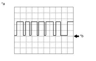
Text in Illustration *a Example *b GND Using an oscilloscope, check waveform 1.
Waveform 1: Item Contents Terminal H28-4 (BRDA) - H28-12 (GND)
H28-5 (BPRG) - H28-12 (GND)
Tool setting 5 V/DIV, 50 μs./DIV. Vehicle condition Ignition switch ON Tech Tips
The waveform shown in the illustration is an example. If the tester displays a waveform that alternates between high and low, where high is a voltage that is between the IG power source voltage and a voltage 2.2 V lower than the IG power source voltage, and where low is a voltage of between 0 and 1.2 V, the ECU can be judged normal.
-