LIGHTING SYSTEM TERMINALS OF ECU
-
CHECK INSTRUMENT PANEL JUNCTION BLOCK ASSEMBLY AND MAIN BODY ECU (NETWORK GATEWAY ECU)
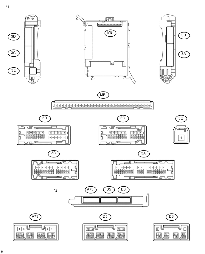
Text in Illustration *1 Instrument Panel Junction Block Assembly *2 Main Body ECU (Network Gateway ECU)
-
Disconnect the D5 main body ECU (network gateway ECU) connectors.
-
Measure the voltage according to the value(s) in the table below.
Terminal No. Wiring Color Terminal Description Condition Specified Condition D5-22 (ACC) - Body ground*1 W - Body ground ACC power supply Ignition switch ACC 11 to 14 V Ignition switch off Below 1 V
-
*1: w/ Entry and Start System
-
-
Disconnect the 3A, 3C, 3E, A73 and D6 instrument panel junction block assembly and main body ECU (network gateway ECU) connectors.
-
Measure the voltage according to the value(s) in the table below.
Terminal No. Wiring Color Terminal Description Condition Specified Condition 3A-15 - Body ground W - Body ground IG power supply Ignition switch ON 11 to 14 V Ignition switch off Below 1 V 3A-20 - Body ground SB - Body ground ACC power supply Ignition switch ACC 11 to 14 V Ignition switch off Below 1 V 3A-27 - Body ground G-R - Body ground Battery power supply Always 11 to 14 V 3C-19 - Body ground L-R - Body ground Battery power supply Always 11 to 14 V 3E-1 - Body ground B-R - Body ground Battery power supply Always 11 to 14 V If the result is not as specified, there may be a malfunction in the wire harness.
-
Measure the resistance according to the value(s) in the table below.
Terminal No. (Symbol) Wiring Color Terminal Description Condition Specified Condition 3A-12 - Body ground B - Body ground Ground Always Below 1 Ω 3A-13 - Body ground B - Body ground Ground Always Below 1 Ω A73-4 (GND) - Body ground B-Y - Body ground Ground Always Below 1 Ω D6-1 (GND) - Body ground B - Body ground Ground Always Below 1 Ω If the result is not as specified, there may be a malfunction in the wire harness.
-
Reconnect the 3A, 3C, 3E, A73 and D6 instrument panel junction block assembly and main body ECU (network gateway ECU) connectors.
-
Measure the voltage and check for pulses according to the value(s) in the table below.
Terminal No. (Symbol) Wiring Color Terminal Description Condition Specified Condition 3A-28 - Body ground V - Body ground Front door courtesy light switch LH input*3
Front door courtesy light switch RH input*4
Front door LH open*3
Front door RH open*4
Below 1 V Front door LH closed*3
Front door RH closed*4
11 to 14 V 3B-13 - Body ground GR - Body ground Front door courtesy light switch RH input*3
Front door courtesy light switch LH input*4
Front door RH open*3
Front door LH open*4
Below 1 V Front door RH closed*3
Front door LH closed*4
11 to 14 V 3D-26 - Body ground SB - Body ground Luggage compartment door courtesy light switch input Luggage compartment door open Below 1 V Luggage compartment door closed 11 to 14 V D5-5 (FLCL) - Body ground*3
D5-5 (FRCL) - Body ground*4
SB - Body ground Front door courtesy light LH drive output*3
Front door courtesy light RH drive output*4
Ignition switch off, front door courtesy light LH off*3
Ignition switch off, front door courtesy light RH off*4
11 to 14 V Ignition switch off, front door courtesy light LH on*3
Ignition switch off, front door courtesy light RH on*4
Below 1 V D5-6 (FRCL) - Body ground*3
D5-6 (FLCL) - Body ground*4
B - Body ground Front door courtesy light RH drive output*3
Front door courtesy light LH drive output*4
Ignition switch off, front door courtesy light RH off*3
Ignition switch off, front door courtesy light LH off*4
11 to 14 V Ignition switch off, front door courtesy light RH on*3
Ignition switch off, front door courtesy light LH on*4
Below 1 V D5-7 (DOMR) - Body ground L - Body ground Illuminated entry drive output (to map light assembly) Map light switch in DOOR position and map light assembly on Below 1 V Map light switch in DOOR position and map light assembly off 11 to 14 V D5-28 (ILL) - Body ground*2 Y - Body ground Ignition key cylinder light drive output Ignition switch off, ignition key cylinder light off (when operated by illuminated entry system) 11 to 14 V Ignition switch off, ignition key cylinder light on (when operated by illuminated entry system) Below 1 V D6-11 (LSFD) - Body ground*1 W - Body ground Front door unlock detection switch LH input*3
Front door unlock detection switch RH input*4
Ignition switch off, all doors closed and front door LH locked*3
Ignition switch off, all doors closed and front door RH locked*4
Pulse generation Front door LH unlocked*3
Front door RH unlocked*4
Below 1 V D6-12 (LSFP) - Body ground*1 SB - Body ground Front door unlock detection switch RH input*3
Front door unlock detection switch LH input*4
Ignition switch off, all doors closed and front door RH locked*3
Ignition switch off, all doors closed and front door LH locked*4
Pulse generation Front door RH unlocked*3
Front door LH unlocked*4
Below 1 V
-
*1: w/ Entry and Start System
-
*2: w/o Entry and Start System
-
*3: for LHD
-
*4: for RHD
If the result is not as specified, the main body ECU (network gateway ECU) or instrument panel junction block assembly may have a malfunction.
-
-
-
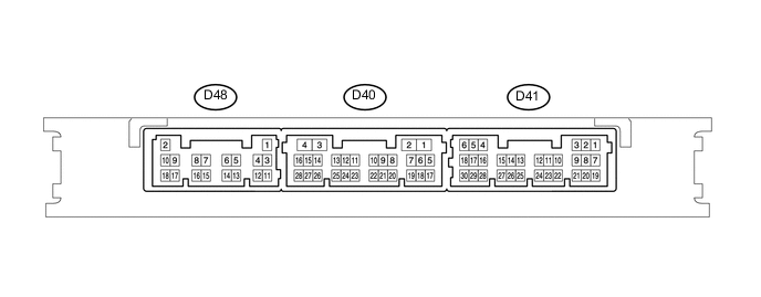
CHECK CERTIFICATION ECU (SMART KEY ECU ASSEMBLY)
-
Disconnect the D41 and D48 certification ECU (smart key ECU assembly) connectors.
-
If the result is not as specified, the certification ECU (smart key ECU assembly) may have a malfunction.
-
-
Measure the voltage according to the value(s) in the table below.
Terminal No. (Symbol) Wiring Color Terminal Description Condition Specified Condition D41-5 (IG2) - Body ground Y - Body ground IG power supply Engine switch on (IG) 11 to 14 V Engine switch off Below 1 V D48-2 (+B) - D48-11 (GND) R - B +B power supply Always 9.5 to 16 V If the result is not as specified, there may be a malfunction in the wire harness.
-
Measure the resistance according to the value(s) in the table below.
Terminal No. (Symbol) Wiring Color Terminal Description Condition Specified Condition D48-11 (GND) - Body ground B - Body ground Ground Always Below 1 Ω If the result is not as specified, there may be a malfunction in the wire harness.
-
Reconnect the D41 and D48 certification ECU (smart key ECU assembly) connectors.
-
Measure the voltage according to the value(s) in the table below.
Terminal No. (Symbol) Wiring Color Terminal Description Condition Specified Condition D41-16 (SWIL) - D41-24 (AGND) LG - B Engine switch illumination drive output Engine switch illumination on 11 to 14 V Engine switch illumination off Below 1 V If the result is not as specified, the certification ECU (smart key ECU assembly) may have a malfunction.
-