ENGINE IMMOBILISER SYSTEM, Diagnostic DTC:B278A
| DTC Code | DTC Name |
|---|---|
| B278A | Short to GND in Immobiliser System Power Source Circuit |
DESCRIPTION
When there is a short to GND in the power supply for the transponder key amplifier of the power switch, the certification ECU (smart key ECU assembly) stores this DTC.
| DTC Code | DTC Detection Condition | Trouble Area | DTC Output Confirmation Operation |
|---|---|---|---|
| B278A | A short to GND in the power supply of the transponder key amplifier of the power switch (VC5 - VC5) (1 trip detection logic*). |
|
With the shift lever in P, the key held near the power switch and a hybrid control system start operation is performed by pressing and holding the power switch when the key battery is depleted. |
-
*: Only output while a malfunction is present.
| Vehicle Condition when Malfunction Detected | Fail-safe Operation when Malfunction Detected |
|---|---|
| Hybrid control system cannot be started when key battery is depleted by holding key near power switch and pressing and holding power switch with shift lever in P | - |
| DTC Code | Data List and Active Test |
|---|---|
| B278A | - |
WIRING DIAGRAM
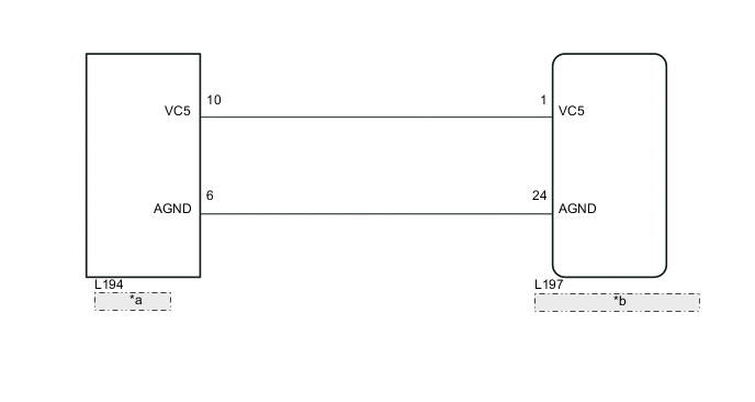
| *a | Power Switch |
| *b | Certification ECU (Smart Key ECU Assembly) |
CAUTION / NOTICE / HINT
Note
-
Before replacing the certification ECU (smart key ECU assembly), refer to Service Bulletin.
-
After performing repairs, perform the operation that fulfills the DTC output confirmation operation, and then confirm that no DTCs are output again.
PROCEDURE
-
CHECK CERTIFICATION ECU (SMART KEY ECU ASSEMBLY)
-
Reconnect the L197 certification ECU (smart key ECU assembly) connectors.
-
Reconnect the L194 power switch connector.
-
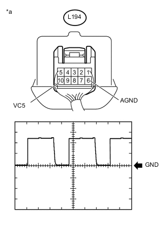
Text in Illustration *a Component with harness connected
(Power Switch)
Using an oscilloscope, check the waveform.
Tech Tips
Perform this inspection on the power switch side.
Measurement Condition Item Content Tester Connection L194-10 (VC5) - L194-6 (AGND) Tool Setting 2 V/DIV., 200 ms./DIV. Condition Power switch off, key not in cabin, within 30 seconds after power switch pressed OK Waveform is output normally (refer to illustration).
OK 
REPLACE POWER SWITCH Click here
NG 
-
-
CHECK HARNESS AND CONNECTOR (CERTIFICATION ECU (SMART KEY ECU ASSEMBLY) - POWER SWITCH)
-
Disconnect the L197 certification ECU (smart key ECU assembly) connectors.
-
Disconnect the L194 power switch connector.
-
Measure the resistance according to the value(s) in the table below.
Standard Resistance Tester Connection Condition Specified Condition L197-1 (VC5) - L194-10 (VC5) Always Below 1 Ω L197-24 (AGND) - L194-6 (AGND) Always Below 1 Ω L194-10 (VC5) or L194-6 (AGND) - Body ground Always 10 kΩ or higher
NG
REPAIR OR REPLACE HARNESS OR CONNECTOR
OK
-
-
CHECK CERTIFICATION ECU (SMART KEY ECU ASSEMBLY)
-
Reconnect the L197 certification ECU (smart key ECU assembly) connector.
-
Reconnect the L194 power switch connector.
-
Measure the voltage according to the value(s) in the table below.
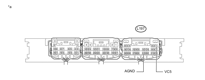
Text in Illustration *a Component with harness connected
(Certification ECU (Smart Key ECU Assembly))
- - Standard Voltage Tester Connection Condition Specified Condition L197-1 (VC5) - L197-24 (AGND) Power switch off, brake pedal not depressed, 30 seconds or more after driver door opened and then closed Below 1 V
OK
REPLACE POWER SWITCH Click here
NG
REPLACE CERTIFICATION ECU (SMART KEY ECU ASSEMBLY)
-