DYNAMIC RADAR CRUISE CONTROL SYSTEM TERMINALS OF ECU
CHECK ECM (for 2AR-FE)
Disconnect the A62 and B77 ECM connectors.

Measure the resistance and voltage according to the value(s) in the table below.
Terminal No. (Symbol)
Wiring Color
Terminal Description
Condition
Specified Condition
A62-11 (STP) - B77-16 (E1)
L - BR
Stop light signal
Brake pedal depressed
7.5 to 14 V
A62-11 (STP) - B77-16 (E1)
L - BR
Stop light signal
Brake pedal released
Below 1.5 V
A62-40 (CCS) - B77-16 (E1)
L - BR
Cruise control switch circuit
Cruise control switch off
1 MΩ or higher
A62-40 (CCS) - B77-16 (E1)
L - BR
Cruise control switch circuit
Cruise control switch on
Below 2.5 Ω
A62-40 (CCS) - B77-16 (E1)
L - BR
Cruise control switch circuit
+RES switch on
235 to 245 Ω
A62-40 (CCS) - B77-16 (E1)
L - BR
Cruise control switch circuit
-SET switch on
617 to 643 Ω
A62-40 (CCS) - B77-16 (E1)
L - BR
Cruise control switch circuit
CANCEL switch on
1509 to 1571 Ω
A62-24 (ST1-) - B77-16 (E1)
GR - BR
Stop light signal
Ignition switch ON, brake pedal depressed
Below 1.5 V
A62-24 (ST1-) - B77-16 (E1)
GR - BR
Stop light signal
Ignition switch ON, brake pedal released
7.5 to 14 V
B77-67 (D) - B77-16 (E1)*1
B - BR
D shift position signal
Ignition switch ON, shift lever in D
11 to 14 V
B77-67 (D) - B77-16 (E1)*1
B - BR
D shift position signal
Ignition switch ON, shift lever is not in D
Below 1 V
B77-67 (D) - B77-16 (E1)*2
L - BR
Clutch switch signal
Ignition switch ON, clutch pedal depressed
11 to 14 V
B77-67 (D) - B77-16 (E1)*2
L - BR
Clutch switch signal
Ignition switch ON, clutch pedal released
Below 1 V
A62-43 (SFTD) - B77-16 (E1)*1
Y - BR
Downshift switch signal
Ignition switch ON and shift lever in S
11 to 14 V
Ignition switch ON and shift lever in "-" (downshift)
Below 1 V
A62-42 (SFTU) - B77-16 (E1)*1
LG - BR
Upshift switch signal
Ignition switch ON and shift lever in S
11 to 14 V
Ignition switch ON and shift lever in "+" (upshift)
Below 1 V
*1: for Automatic Transaxle
*2: for Manual Transaxle
CHECK ECM (for 3ZR-FE (K111))
Disconnect the A62 and B75 ECM connectors.
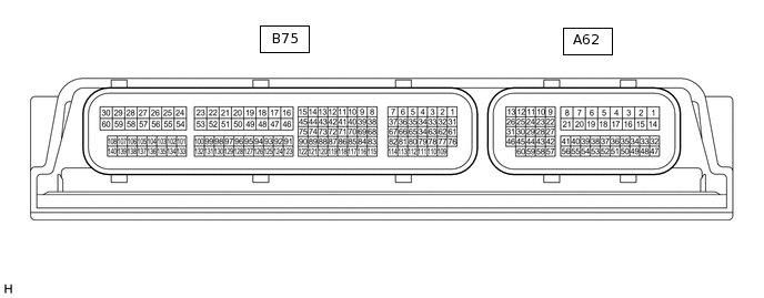
Measure the resistance and voltage according to the value(s) in the table below.
Terminal No. (Symbol)
Wiring Color
Terminal Description
Condition
Specified Condition
A62-9 (STP) - B75-16 (E1)
L - BR
Stop light signal
Brake pedal depressed
7.5 to 14 V
A62-9 (STP) - B75-16 (E1)
L - BR
Stop light signal
Brake pedal released
Below 1.5 V
A62-60 (CCS) - B75-16 (E1)
L - BR
Cruise control switch circuit
Cruise control switch off
1 MΩ or higher
A62-60 (CCS) - B75-16 (E1)
L - BR
Cruise control switch circuit
Cruise control switch on
Below 2.5 Ω
A62-60 (CCS) - B75-16 (E1)
L - BR
Cruise control switch circuit
+RES switch on
235 to 245 Ω
A62-60 (CCS) - B75-16 (E1)
L - BR
Cruise control switch circuit
-SET switch on
617 to 643 Ω
A62-60 (CCS) - B75-16 (E1)
L - BR
Cruise control switch circuit
CANCEL switch on
1509 to 1571 Ω
A62-10 (ST1-) - B75-16 (E1)
GR - BR
Stop light signal
Ignition switch ON, brake pedal depressed
Below 1.5 V
A62-10 (ST1-) - B75-16 (E1)
GR - BR
Stop light signal
Ignition switch ON, brake pedal released
7.5 to 14 V
B75-81 (D) - B75-16 (E1)
B - BR
D shift position signal
Ignition switch ON, shift lever in D
11 to 14 V
B75-81 (D) - B75-16 (E1)
B - BR
D shift position signal
Ignition switch ON, shift lever is not in D
Below 1 V
A62-43 (SFTD) - B75-16 (E1)
Y - BR
Downshift switch signal
Ignition switch ON and shift lever in M
11 to 14 V
A62-43 (SFTD) - B75-16 (E1)
Y - BR
Downshift switch signal
Ignition switch ON and shift lever in "-" (downshift)
Below 1 V
A62-42 (SFTU) - B75-16 (E1)
LG - BR
Upshift switch signal
Ignition switch ON and shift lever in M
11 to 14 V
A62-42 (SFTU) - B75-16 (E1)
LG - BR
Upshift switch signal
Ignition switch ON and shift lever in "+" (upshift)
Below 1 V
CHECK ECM (for 3ZR-FAE, 3ZR-FE (except K111))
Disconnect the A62 and B93 ECM connectors.

Measure the resistance and voltage according to the value(s) in the table below.
Terminal No. (Symbol)
Wiring Color
Terminal Description
Condition
Specified Condition
A62-9 (STP) - B93-16 (E1)
L - BR
Stop light signal
Brake pedal depressed
7.5 to 14 V
A62-9 (STP) - B93-16 (E1)
L - BR
Stop light signal
Brake pedal released
Below 1.5 V
A62-36 (CCS) - A62-35 (ECCS)
L - BR
Cruise control switch circuit
Cruise control switch off
1 MΩ or higher
A62-36 (CCS) - A62-35 (ECCS)
L - BR
Cruise control switch circuit
Cruise control switch on
Below 2.5 Ω
A62-36 (CCS) - A62-35 (ECCS)
L - BR
Cruise control switch circuit
+RES switch on
235 to 245 Ω
A62-36 (CCS) - A62-35 (ECCS)
L - BR
Cruise control switch circuit
-SET switch on
617 to 643 Ω
A62-36 (CCS) - A62-35 (ECCS)
L - BR
Cruise control switch circuit
CANCEL switch on
1509 to 1571 Ω
A62-10 (ST1-) - B93-16 (E1)
GR - BR
Stop light signal
Ignition switch ON, brake pedal depressed
Below 1.5 V
A62-10 (ST1-) - B93-16 (E1)
GR - BR
Stop light signal
Ignition switch ON, brake pedal released
7.5 to 14 V
B93-65 (D) - B93-16 (E1)*1
B - BR
D shift position signal
Ignition switch ON, shift lever in D
11 to 14 V
B93-65 (D) - B93-16 (E1)*1
B - BR
D shift position signal
Ignition switch ON, shift lever is not in D
Below 1 V
B93-65 (D) - B93-16 (E1)*2
L - BR
Clutch switch signal
Ignition switch ON, clutch pedal depressed
11 to 14 V
B93-65 (D) - B93-16 (E1)*2
L - BR
Clutch switch signal
Ignition switch ON, clutch pedal released
Below 1 V
A62-43 (SFTD) - B93-16 (E1)*1
Y - BR
Downshift switch signal
Ignition switch ON and shift lever in M
11 to 14 V
A62-43 (SFTD) - B93-16 (E1)*1, *3
Y - BR
Downshift switch signal
Ignition switch ON and "-" shift paddle operated and held (downshift)
Below 1 V
A62-43 (SFTD) - B93-16 (E1)*1
Y - BR
Downshift switch signal
Ignition switch ON and shift lever in "-" (downshift)
Below 1 V
A62-42 (SFTU) - B93-16 (E1)*1
LG - BR
Upshift switch signal
Ignition switch ON and shift lever in M
11 to 14 V
A62-42 (SFTU) - B93-16 (E1)*1, *3
LG - BR
Upshift switch signal
Ignition switch ON and "+" shift paddle operated and held (upshift)
Below 1 V
A62-42 (SFTU) - B93-16 (E1)*1
LG - BR
Upshift switch signal
Ignition switch ON and shift lever in "+" (upshift)
Below 1 V
*1: for CVT
*2: for Manual Transaxle
*3: w/ Shift Paddle Switch
CHECK ECM (for 2AD-FHV, 2AD-FTV)
Disconnect the A61 and B76 ECM connectors.
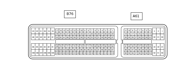
Measure the resistance and voltage according tothe value(s) in the table below.
Terminal No. (Symbol)
Wiring Color
Terminal Description
Condition
Specified Condition
A61-35 (STP) - B76-109 (E1)
L - BR
Stop light signal
Brake pedal depressed
7.5 to 14 V
A61-35 (STP) - B76-109 (E1)
L - BR
Stop light signal
Brake pedal released
0 to 1.5 V
A61-23 (CCS) - B76-109 (E1)
L - BR
Cruise control switch circuit
Cruise control switch off
1 MΩ or higher
A61-23 (CCS) - B76-109 (E1)
L - BR
Cruise control switch circuit
Cruise control switch on
Below 2.5 Ω
A61-23 (CCS) - B76-109 (E1)
L - BR
Cruise control switch circuit
+RES switch on
235 to 245 Ω
A61-23 (CCS) - B76-109 (E1)
L - BR
Cruise control switch circuit
-SET switch on
617 to 643 Ω
A61-23 (CCS) - B76-109 (E1)
L - BR
Cruise control switch circuit
CANCEL switch on
1509 to 1571 Ω
A61-34 (ST1-) - B76-109 (E1)
GR - BR
Stop light signal
Ignition switch ON, brake pedal depressed
0 to 1.5 V
A61-34 (ST1-) - B76-109 (E1)
GR - BR
Stop light signal
Ignition switch ON, brake pedal released
7.5 to 14 V
B76-73 (D) - B76-109 (E1)*1
B - BR
D shift position signal
Ignition switch ON, shift lever in D
11 to 14 V
B76-73 (D) - B76-109 (E1)*1
B - BR
D shift position signal
Ignition switch ON, shift lever is not in D
Below 1 V
B76-73 (D) - B76-109 (E1)*2
L - BR
Clutch switch signal
Ignition switch ON, clutch pedal depressed
11 to 14 V
B76-73 (D) - B76-109 (E1)*2
L - BR
Clutch switch signal
Ignition switch ON, clutch pedal released
Below 1 V
A61-28 (SFTD) - B76-109 (E1)*1
Y - BR
Downshift switch signal
Ignition switch ON and shift lever in M
11 to 14 V
A61-28 (SFTD) - B76-109 (E1)*1
Y - BR
Downshift switch signal
Ignition switch ON and shift lever in "-" (downshift)
Below 1 V
B76-61 (SFTU) - B76-109 (E1)*1
LG - BR
Upshift switch signal
Ignition switch ON and shift lever in M
11 to 14 V
B76-61 (SFTU) - B76-109 (E1)*1
LG - BR
Upshift switch signal
Ignition switch ON and shift lever in "+" (upshift)
Below 1 V
*1: for Automatic Transaxle
*2: for Manual Transaxle
CHECK ECM (for 2WW)
Disconnect the A62 and B112 ECM connectors.
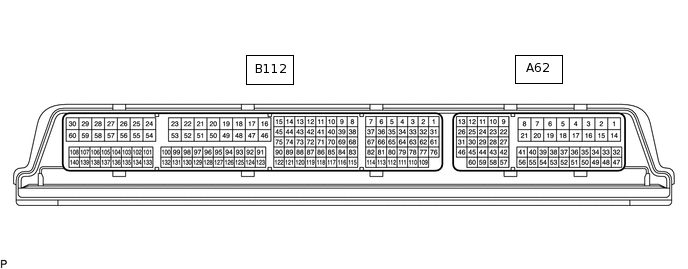
Measure the resistance and voltage according tothe value(s) in the table below.
Terminal No. (Symbol)
Wiring Color
Terminal Description
Condition
Specified Condition
A62-48 (STP) - A62-4 (E1)
L - W-B
Stop light signal
Brake pedal depressed
7.5 to 14 V
A62-48 (STP) - A62-4 (E1)
L - W-B
Stop light signal
Brake pedal released
0 to 1.5 V
A62-41 (CCS) - A62-42 (ECCS)
L - BR
Cruise control switch circuit
Cruise control switch off
1 MΩ or higher
A62-41 (CCS) - A62-42 (ECCS)
L - BR
Cruise control switch circuit
Cruise control switch on
Below 2.5 Ω
A62-41 (CCS) - A62-42 (ECCS)
L - BR
Cruise control switch circuit
+RES switch on
235 to 245 Ω
A62-41 (CCS) - A62-42 (ECCS)
L - BR
Cruise control switch circuit
-SET switch on
617 to 643 Ω
A62-41 (CCS) - A62-42 (ECCS)
L - BR
Cruise control switch circuit
CANCEL switch on
1509 to 1571 Ω
A62-10 (ST1-) - A62-4 (E1)
GR - W-B
Stop light signal
Ignition switch ON, brake pedal depressed
0 to 1.5 V
A62-10 (ST1-) - A62-4 (E1)
GR - W-B
Stop light signal
Ignition switch ON, brake pedal released
7.5 to 14 V
A62-7 (D) - A62-4 (E1)
L - W-B
Clutch switch signal
Ignition switch ON, clutch pedal depressed
11 to 14 V
A62-7 (D) - A62-4 (E1)
L - W-B
Clutch switch signal
Ignition switch ON, clutch pedal released
Below 1 V
CHECK DRIVING SUPPORT ECU ASSEMBLY

Terminal No. (Symbol)
Wiring Color
Terminal Description
Condition
Specified Condition
G168-3 (BZ) - G168-28 (GND)
LG - BR
Skid control buzzer output
Ignition switch ON, buzzer not sounding
11 to 14 V
G168-7 (B) - G168-28 (GND)
B*1 - BR
V*2 - BR
Power source
Ignition switch ON
11 to 14 V
G168-8 (CA1P) - G168-28 (GND)
B - BR
CAN communication signal
Ignition switch ON
Pulse generation
(See waveform 1)
G168-9 (CA1N) - G168-28 (GND)
W - BR
CAN communication signal
Ignition switch ON
Pulse generation
(See waveform 2)
G168-10 (CA2H) - G168-28 (GND)
P - BR
CAN communication signal
Ignition switch ON
Pulse generation
(See waveform 1)
G168-11 (CA2L) - G168-28 (GND)
LG - BR
CAN communication signal
Ignition switch ON
Pulse generation
(See waveform 2)
G168-23 (SPSW) - G168-28 (GND)
B - BR
Steering pad switch signal (Distance control switch signal)
Ignition switch ON, Distance control switch on
Below 1 Ω
G168-23 (SPSW) - G168-28 (GND)
B - BR
Steering pad switch signal (Distance control switch signal)
Ignition switch ON, Distance control switch off
4.75 to 5.25 V
G168-28 (GND) - Body ground
BR - Body ground
Ground
Always
Below 1 Ω
*1: w/o Stop and Start System
*2: w/ Stop and Start System
-
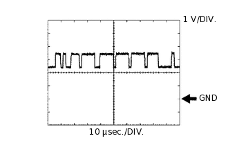
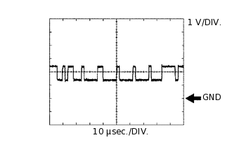
Waveform 1
CAN communication signal
Item
Content
Terminal Name
Between G168-8 (CA1P) and G168-28 (GND)
Between G168-10 (CA2H) and G168-28 (GND)
Tester Range
1 V/DIV., 10 μsec./DIV.
Condition
Ignition switch ON
Tip:The waveform varies depending on the CAN communication signal.
-
Waveform 2
CAN communication signal
Item
Content
Terminal Name
Between G168-9 (CA1N) and G168-28 (GND)
Between G168-11 (CA2L) and G168-28 (GND)
Tester Range
1 V/DIV., 10 μsec./DIV.
Condition
Ignition switch ON
Tip:The waveform varies depending on the CAN communication signal.
CHECK MILLIMETER WAVE RADAR SENSOR

Terminal No. (Symbol)
Wiring Color
Terminal Description
Condition
Specified Condition
Z6-1 (SGND) - Body ground
BR - Body ground
Ground
Always
Below 1 Ω
Z6-2 (CA2L) - Z6-1 (SGND)
LG - BR
CAN communication signal
Ignition switch ON
Pulse generation
(See waveform 2)
Z6-3 (CA2H) - Z6-1 (SGND)
B - BR
CAN communication signal
Ignition switch ON
Pulse generation
(See waveform 1)
Z6-5 (CA1P) - Z6-1 (SGND)
SB - BR
CAN communication signal
Ignition switch ON
Pulse generation
(See waveform 1)
Z6-6 (CA1N) - Z6-1 (SGND)
W - BR
CAN communication signal
Ignition switch ON
Pulse generation
(See waveform 2)
Z6-8 (IGB) - Z6-1 (SGND)
L - BR
Power source
Ignition switch ON
11 to 14 V
-
Waveform 1
CAN communication signal
Item
Content
Terminal Name
Between Z6-3 (CA2H) and Z6-1 (SGND)
Between Z6-5 (CA1P) and Z6-1 (SGND)
Tester Range
1 V/DIV., 10 μsec./DIV.
Condition
Ignition switch ON
Tip:The waveform varies depending on the CAN communication signal.
-
Waveform 2
CAN communication signal
Item
Content
Terminal Name
Between Z6-2 (CA2L) and Z6-1 (SGND)
Between Z6-6 (CA1N) and Z6-1 (SGND)
Tester Range
1 V/DIV., 10 μsec./DIV.
Condition
Ignition switch ON
Tip:The waveform varies depending on the CAN communication signal.
-