INVERTER WITH CONVERTER INSTALLATION
CAUTION / NOTICE / HINT
When replacing with a new inverter with converter assembly, securely lock the retainer of the inverter cooling hose since it is not locked.
Before replacing the wire harness boot, check if any DTCs are output.
Remove the tape that was attached to the hose at removal in accordance with the installation procedure.
PROCEDURE
INSTALL NO. 2 ENGINE ROOM WIRE
Install the No. 2 engine room wire with the nut.
18 N*m
184 kgf*cm
13 ft.*lbf
Note:Temporarily install the nut by hand, then tighten using a tool.
Close the terminal cap.
INSTALL NO. 2 INVERTER RESERVE TANK BRACKET
Install the No. 2 inverter reserve tank bracket to the inverter with converter assembly with the 2 bolts.
10 N*m
102 kgf*cm
7 ft.*lbf
INSTALL HYBRID INVERTER PROTECTOR ASSEMBLY (for AWD)
Install the hybrid inverter protector assembly to the inverter with converter assembly with the 2 bolts.
10 N*m
102 kgf*cm
7 ft.*lbf
INSTALL WIRE HARNESS CLAMP BRACKET (for AWD)
Install the wire harness clamp bracket to the inverter with converter assembly with the bolt.
7.7 N*m
79 kgf*cm
68 in.*lbf
INSTALL NO. 3 INVERTER BRACKET
-
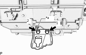
*a
Stopper
Temporarily install the No. 3 inverter bracket to the inverter with converter assembly with the 2 bolts.
Tip:When installing, align with the stopper.
Tighten the 2 bolts in the sequence shown in the illustration.
3.5 N*m
36 kgf*cm
31 in.*lbf
-
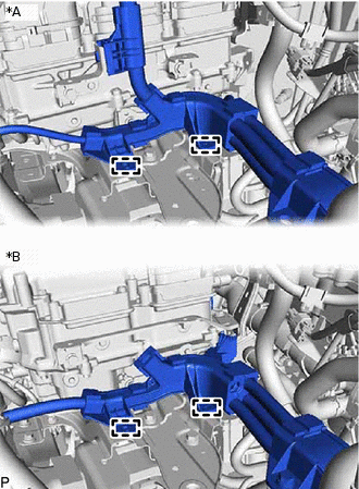
INSTALL NO. 2 INVERTER BRACKET
-
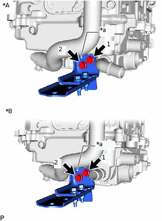
*A
for AWD
*B
for 2WD
*a
Stopper
Temporarily install the No. 2 inverter bracket to the inverter with converter assembly with the 2 bolts.
Tip:When installing, align with the stopper.
Tighten the 2 bolts in the sequence shown in the illustration.
3.5 N*m
36 kgf*cm
31 in.*lbf
-
INSTALL NO. 4 INVERTER BRACKET
-
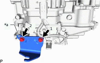
*a
Stopper
Temporarily install the No. 4 inverter bracket to the inverter with converter assembly with the 2 bolts.
Tip:When installing, align with the stopper.
Tighten the 2 bolts in the sequence shown in the illustration.
3.5 N*m
36 kgf*cm
31 in.*lbf
-
INSTALL AIR CLEANER BRACKET (for AWD)
Install the air cleaner bracket to the inverter with converter assembly with the bolt.
5.0 N*m
51 kgf*cm
44 in.*lbf
INSTALL NO. 1 AIR CLEANER BRACKET
for AWD:
Install the No. 1 air cleaner bracket to the inverter with converter assembly with the bolt.
5.0 N*m
51 kgf*cm
44 in.*lbf
for 2WD:
Install the No. 1 air cleaner bracket to the inverter with converter assembly with the 2 bolts.
5.0 N*m
51 kgf*cm
44 in.*lbf
INSTALL HIGH VOLTAGE FUSE
CAUTION:Be sure to wear insulated gloves.
Tip:Perform this procedure only when replacement of the high voltage fuse is necessary.
Remove the bolt and connector cover assembly.
Install the high voltage fuse with 2 new nuts.
4.0 N*m
41 kgf*cm
35 in.*lbf
Note:Be sure to use a torque wrench to tighten the nuts.
Temporarily install the connector cover assembly with the bolt to prevent any foreign objects or water from entering the inverter with converter assembly.
INSTALL INVERTER WITH CONVERTER ASSEMBLY
CAUTION:Be sure to wear insulated gloves.
Note:Since the inverter with converter assembly is very heavy, 2 people are needed to install it on the vehicle. Take care not to damage surrounding parts.
To prevent damage, do not hold the connectors when lifting up the inverter with converter assembly.
To prevent damage caused by static electricity, do not touch the terminals at the openings of disconnected connectors.
Temporarily install the No. 6 inverter bracket with the 2 bolts.
Temporarily install the inverter with converter assembly with the 2 nuts and bolt.
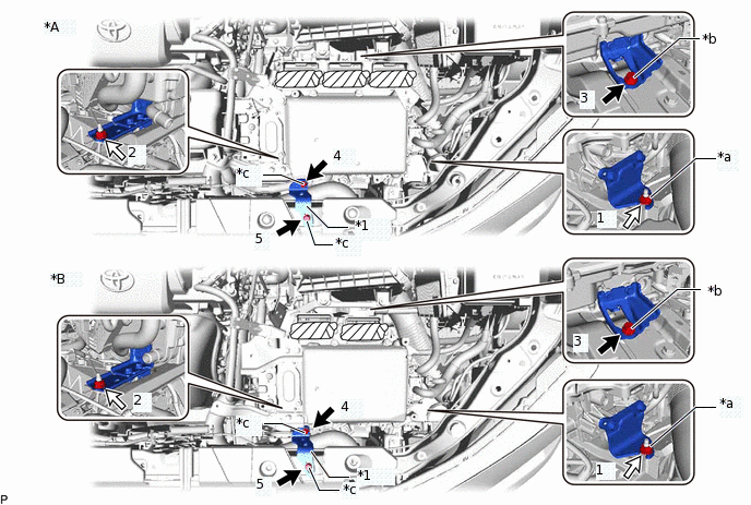
*A
for AWD
*B
for 2WD
*1
No. 6 Inverter Bracket
-
-
*a
The stud bolt must firmly contact the inverter bracket stay.
*b
Bolt A
*c
Bolt B
-
-

Bolt

Nut
Tighten the 2 nuts and 3 bolts in the order shown in the illustration.
Bolt A
13 N*m
133 kgf*cm
10 ft.*lbf
Bolt B
10.5 N*m
107 kgf*cm
8 ft.*lbf
Nut
13 N*m
133 kgf*cm
10 ft.*lbf
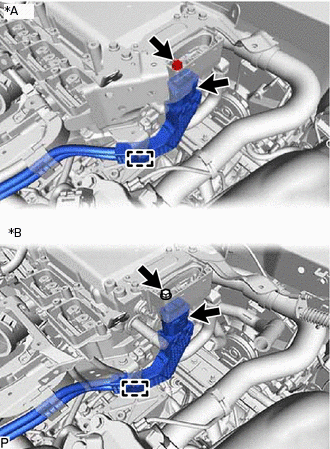
CONNECT NO. 2 INVERTER COOLING HOSE ASSEMBLY
Connect the No. 2 inverter cooling hose assembly, and slide the retainer as shown in the illustration to secure.
Note:Push in the retainer until it clicks in place.
Pull the hose to check that it is securely connected.
If there is foreign matter on the retainer, clean it with water and finger scouring.
Until immediately before connecting the water hose, plug the pipe with vinyl tape, etc. to prevent foreign matter from entering the cooling path.
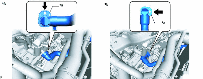
*A
for AWD
*B
for 2WD
*a
Retainer
-
-
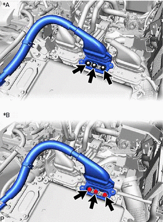
CONNECT NO. 2 ENGINE ROOM WIRE
-
Attach the 2 claws, and connect the No. 2 engine room wire to the junction block.
Connect the No. 2 engine room wire with the nut.
8.4 N*m
86 kgf*cm
74 in.*lbf
Install the relay block cover.
-
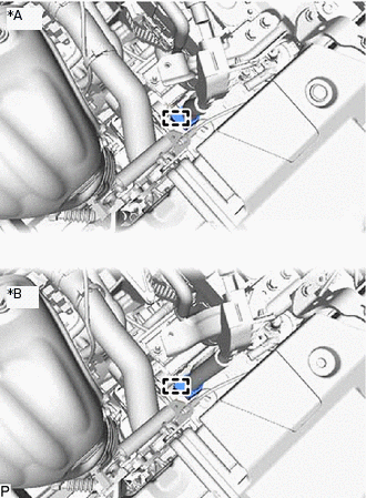
CONNECT LOW VOLTAGE CONNECTOR
-

Install in this direction
Connect the low voltage connector, and lock the connectors with the lock lever.
Note:Do not allow any foreign objects or water to enter the inverter with converter assembly.
The connectors should be connected securely.
The connectors must be securely locked.
Connect the 2 low voltage connectors.
Note:Do not allow any foreign objects or water to enter the inverter with converter assembly.
The connectors should be connected securely.
The connectors must be securely locked.
-
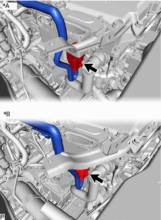
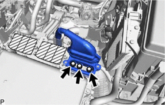
INSTALL INVERTER PROTECTOR (w/ Bracket)
-
*a
Stopper
Install the inverter protector with the bolt.
8.0 N*m
82 kgf*cm
71 in.*lbf
Tip:When installing, align with the stopper.
-
CONNECT NO. 5 FLOOR WIRE
CAUTION:Be sure to wear insulated gloves.
Note:When connecting the No. 5 floor wire, do not damage the terminals, connector housing and inverter with converter assembly.
Do not touch the connector rubber seal and terminal.
Do not allow any foreign objects or water to enter the inverter with converter assembly.
The connectors should be connected securely.
The connectors must be securely locked.
Remove the bolt and connector cover assembly.
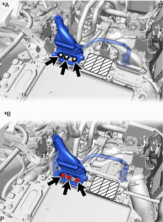
-
*A
for AWD
*B
for 2WD
Connect the No. 5 floor wire to the inverter with converter assembly with the clamp.
Secure the No. 5 floor wire to the inverter with converter assembly with the bolt.
8.0 N*m
82 kgf*cm
71 in.*lbf
CONNECT ENGINE WIRE
CAUTION:Be sure to wear insulated gloves.
Note:When connecting the engine wire, do not damage the terminals, connector housing and inverter with converter assembly.
Do not touch the connector rubber seal and terminal.
Do not allow any foreign objects or water to enter the inverter with converter assembly.
The connectors should be connected securely.
The connectors must be securely locked.
-
*A
for AWD
*B
for 2WD
Connect the engine wire to the inverter with converter assembly.
INSTALL CONNECTOR COVER ASSEMBLY
CAUTION:Be sure to wear insulated gloves.
Using an insulated tool, install the connector cover assembly with the 2 bolts.
8.0 N*m
82 kgf*cm
71 in.*lbf
Note:Make sure that the interlock is fully engaged.
INSTALL NO. 1 INVERTER RESERVE TANK BRACKET (for 2WD)
Install the No. 1 inverter reserve tank bracket to the inverter with converter assembly with the 2 bolts.
10 N*m
102 kgf*cm
7 ft.*lbf
INSTALL NO. 5 FLOOR WIRE
CAUTION:Be sure to wear insulated gloves.
Note:When connecting the No. 5 floor wire, do not damage the terminals, connector housing and inverter with converter assembly.
Do not touch the connector rubber seal and terminal.
Do not allow any foreign objects or water to enter the inverter with converter assembly.
Before replacing the wire harness boot, check if any DTCs are output.
for AWD:
-
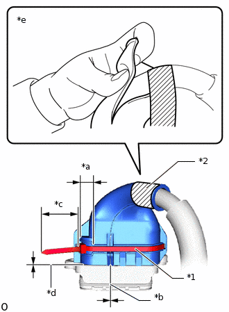
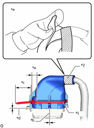
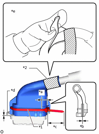
*1
Tie Band
*2
Insulating Tape
*a
Stopper Installation Range
*b
No Gap
*c
9.7 cm or more
*d
2 mm
*e
Wrapping Insulating Tape around the wire 1 time
Install new Tie Band to the wire harness boot as shown in the illustration.
Note:Use the Tie Band included with the part.
Tip:Install the stopper of the Tie Band inside the range shown in the illustration.
Tighten the Tie Band so that there are no gaps in the wire harness boot.
When tightening the tie band, make sure that the protrusion amount of the tie band is 9.7 cm or more.
Make sure that the gap between the wire harness boot and connector is less than 2 mm.
Keep the cutting margin of the tie band within 3 mm.
After wrapping a new insulating tape around the wire 1 time, wrap insulating tape around the connector cover 3 or 4 times as shown in the illustration.
Note:Use the insulating tape included with the part.
Tip:Wrap areas where the wire is exposed with insulating tape.
Apply insulating tape so that there are no gaps in the wire harness boot.
Ensure that tape with a width of approximately 1.5 mm or more is used.
-
-
for AWD:
Connect the No. 5 floor wire (rear motor high-voltage cable side) to the air cleaner bracket, and secure with the clamp.
-
*A
for AWD
*B
for 2WD
Secure the No. 5 floor wire.
Attach the 2 clamps.
-
for AWD:
Using an insulated tool, secure the No. 5 floor wire to the inverter with converter assembly with the 3 bolts.
8.0 N*m
82 kgf*cm
71 in.*lbf
Note:Make sure that the terminal is installed securely.
Make sure that the bolts are fully tightened.
INSTALL UPPER INVERTER COVER (for AWD)
CAUTION:Be sure to wear insulated gloves.
Using an insulated tool, install the upper inverter cover (rear motor high-voltage cable side) with the 2 bolts.
8.0 N*m
82 kgf*cm
71 in.*lbf
Note:Do not touch the rubber seal of the upper inverter cover.
Confirm that the rubber seal of the upper inverter cover is securely installed, then install the cover.
Make sure that the interlock is fully engaged.
When Removing and Installing the bolt, make sure that the tool does not interfere with the wire harness boot.
CONNECT MOTOR CABLE
CAUTION:Be sure to wear insulated gloves.
Note:When connecting the motor cable, do not damage the terminals, connector housing and inverter with converter assembly.
Do not touch the connector rubber seal and terminal.
Do not allow any foreign objects or water to enter the inverter with converter assembly.
Before replacing the wire harness boot, check if any DTCs are output.
-
*1
Tie Band
*2
Insulating Tape
*a
Stopper Installation Range
*b
No Gap
*c
9.7 cm or more
*d
2 mm
*e
Wrapping Insulating Tape around the wire 1 time
Install new Tie Band to the wire harness boot as shown in the illustration.
Note:Use the Tie Band included with the part.
Tip:Install the stopper of the Tie Band inside the range shown in the illustration.
Tighten the Tie Band so that there are no gaps in the wire harness boot.
When tightening the tie band, make sure that the protrusion amount of the tie band is 9.7 cm or more.
Make sure that the gap between the wire harness boot and connector is less than 2 mm.
Keep the cutting margin of the tie band within 3 mm.
After wrapping a new insulating tape around the wire 1 time, wrap insulating tape around the connector cover 3 or 4 times as shown in the illustration.
Note:Use the insulating tape included with the part.
Tip:Wrap areas where the wire is exposed with insulating tape.
Apply insulating tape so that there are no gaps in the wire harness boot.
Ensure that tape with a width of approximately 1.5 mm or more is used.
-
*A
for AWD
*B
for 2WD
Connect the motor cable to the inverter with converter assembly, and secure with the clamp.
Using an insulated tool, secure the motor cable to the inverter with converter assembly with the 3 bolts.
8.0 N*m
82 kgf*cm
71 in.*lbf
Note:Make sure that the terminal is installed securely.
Make sure that the bolts are fully tightened.
INSTALL UPPER INVERTER COVER
CAUTION:Be sure to wear insulated gloves.
Using an insulated tool, install the upper inverter cover (motor cable side) with the 2 bolts.
8.0 N*m
82 kgf*cm
71 in.*lbf
Note:Do not touch the rubber seal of the upper inverter cover.
Confirm that the rubber seal of the upper inverter cover is securely installed, then install the cover.
Make sure that the interlock is fully engaged.
When Removing and Installing the bolt, make sure that the tool does not interfere with the wire harness boot.
CONNECT GENERATOR CABLE
CAUTION:Be sure to wear insulated gloves.
Note:When connecting the motor cable, do not damage the terminals, connector housing and inverter with converter assembly.
Do not touch the connector rubber seal and terminal.
Do not allow any foreign objects or water to enter the inverter with converter assembly.
Before replacing the wire harness boot, check if any DTCs are output.
-
*1
Tie Band
*2
Insulating Tape
*a
Stopper Installation Range
*b
No Gap
*c
9.7 cm or more
*d
2 mm
*e
Wrapping Insulating Tape around the wire 1 time
Install new Tie Band to the wire harness boot as shown in the illustration.
Note:Use the Tie Band included with the part.
Tip:Install the stopper of the Tie Band inside the range shown in the illustration.
Tighten the Tie Band so that there are no gaps in the wire harness boot.
When tightening the tie band, make sure that the protrusion amount of the tie band is 9.7 cm or more.
Make sure that the gap between the wire harness boot and connector is less than 2 mm.
Keep the cutting margin of the tie band within 3 mm.
After wrapping a new insulating tape around the wire 1 time, wrap insulating tape around the connector cover 3 or 4 times as shown in the illustration.
Note:Use the insulating tape included with the part.
Tip:Wrap areas where the wire is exposed with insulating tape.
Apply insulating tape so that there are no gaps in the wire harness boot.
Ensure that tape with a width of approximately 1.5 mm or more is used.
Use the insulating tape included with the part.
-
*A
for AWD
*B
for 2WD
Connect the generator cable to the inverter with converter assembly, and secure with the clamp.
-
*A
for AWD
*B
for 2WD
Using an insulated tool, secure the generator cable to the inverter with converter assembly with the 3 bolts.
8.0 N*m
82 kgf*cm
71 in.*lbf
Note:Make sure that the terminal is installed securely.
Make sure that the bolts are fully tightened.
INSTALL UPPER INVERTER COVER
CAUTION:Be sure to wear insulated gloves.
Using an insulated tool, install the upper inverter cover (generator cable side) with the 2 bolts.
8.0 N*m
82 kgf*cm
71 in.*lbf
Note:Do not touch the rubber seal of the upper inverter cover.
Confirm that the rubber seal of the upper inverter cover is securely installed, then install the cover.
Make sure that the interlock is fully engaged.
When Removing and Installing the bolt, make sure that the tool does not interfere with the wire harness boot.
INSTALL AIR CLEANER CASE SUB-ASSEMBLY
INSTALL AIR CLEANER FILTER ELEMENT SUB-ASSEMBLY
INSTALL AIR CLEANER CAP SUB-ASSEMBLY
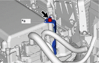
INSTALL INVERTER RESERVE TANK ASSEMBLY
-
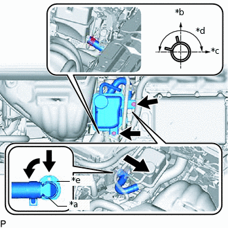
*a
Quick Connector
*b
Top
*c
Right Side of the Vehicle
*d
180°
*e
Retainer
Connect the No. 1 inverter cooling hose assembly, and slide the retainer as shown in the illustration to secure.
Note:Push in the retainer until it clicks in place.
Pull the No. 1 inverter cooling hose assembly to check that it is securely connected.
If there is foreign matter on the retainer, clean it with water and finger scouring.
Until immediately before connecting the water hose, secure the cover with a plastic bag and tape, etc. to prevent foreign matter from entering the cooling path.
Tip:When installing the quick connector, first turn it to the left, then return it to the right, and lock the retainer at the position where the retainer is facing up.
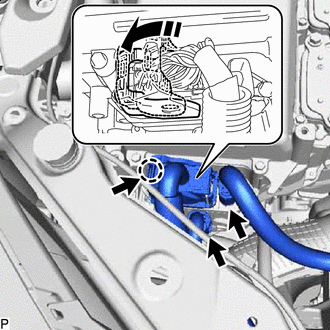
Connect the inverter water hose to the inverter reserve tank sub-assembly, and secure with the hose clamp.
Tip:Align the hose clamp at the position shown in the illustration.
Install the inverter reserve tank sub-assembly with the 2 bolts.
10 N*m
102 kgf*cm
7 ft.*lbf
-
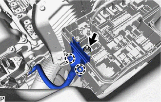
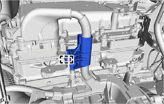
CONNECT WIRE HARNESS
Secure the 4 wire harness clamps to the inverter reserve tank sub-assembly and inverter with converter assembly.
INSTALL SERVICE PLUG GRIP
ADD COOLANT (for Inverter Coolant)
INSPECT FOR COOLANT LEAK (for Inverter Coolant)