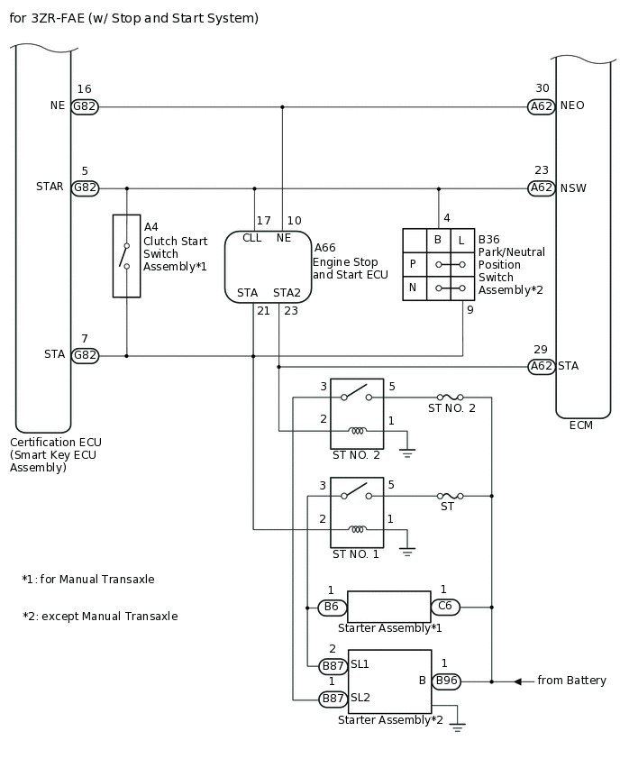
ENTRY AND START SYSTEM(for Start Function) SYSTEM DIAGRAM
Component |
Outline |
|---|---|
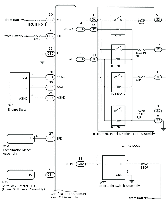
Engine switch
|
|
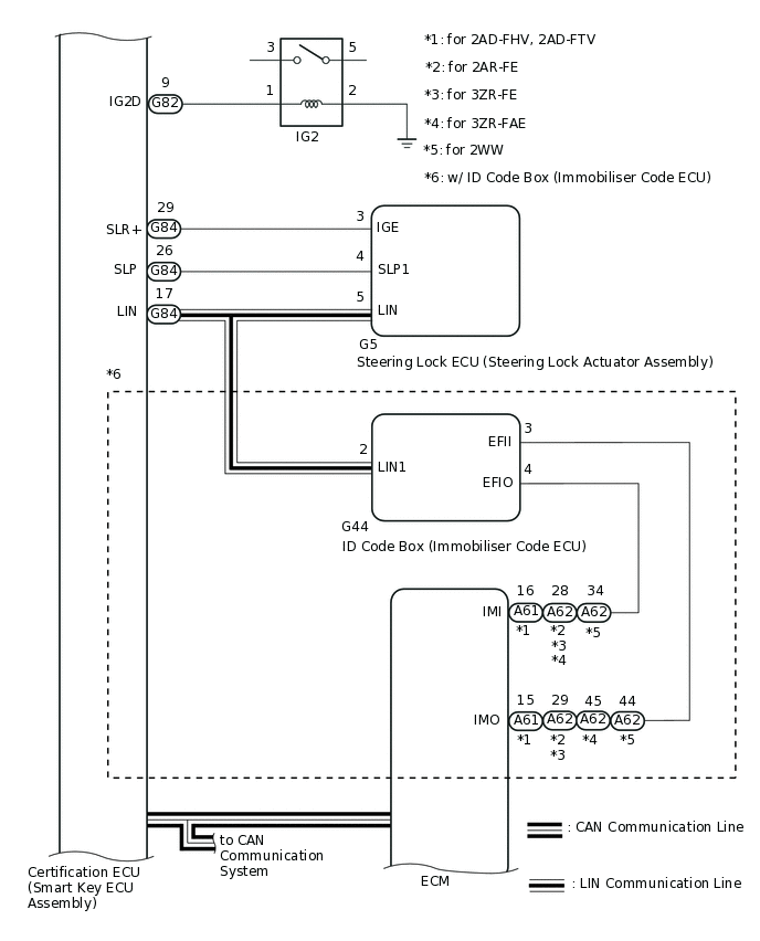
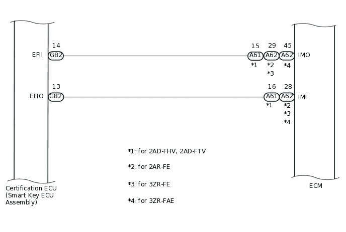
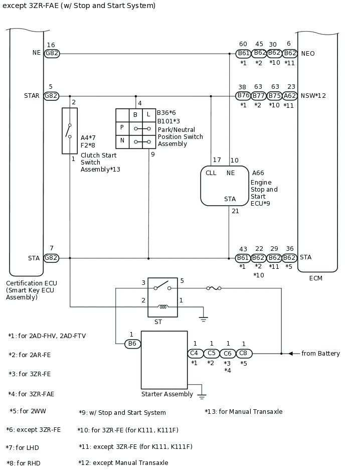
Certification ECU (smart key ECU assembly) |
|
ID code box (immobiliser code ECU)*2 |
|
ECM |
Outputs a signal indicating that the engine has started to the certification ECU (smart key ECU assembly) when starting the engine. |
Steering lock ECU (steering lock actuator assembly) |
|
Combination meter assembly |
|
IG, ACC relay |
Turns on/off according to the certification ECU (smart key ECU assembly) and provides power to each system. |
Stop light switch assembly*3 |
Detects that the brake pedal has been depressed (switch is on) and outputs a signal to the certification ECU (smart key ECU assembly). |
Clutch start switch assembly*4 |
Detects that the clutch pedal has been depressed (switch is on) and outputs a signal to the certification ECU (smart key ECU assembly). |
No. 1 indoor electrical key antenna assembly (front floor) No. 2 indoor electrical key antenna assembly (rear floor) No. 3 indoor electrical key antenna assembly (rear floor) |
Sends the request code from the certification ECU (smart key ECU assembly) and forms the vehicle interior detection area. |
Door control receiver |
Receives the entry and start system code/wireless code sent from the key and sends it to the certification ECU (smart key ECU assembly). |
Electrical key transmitter sub-assembly |
Sends the ID code upon receiving a request signal. |
*1: w/o ID Code Box (Immobiliser Code ECU)
*2: w/ ID Code Box (Immobiliser Code ECU)
*3: except Manual Transaxle
*4: for Manual Transaxle