WINDOW DEFOGGER SYSTEM TERMINALS OF ECU
-
CHECK AIR CONDITIONING AMPLIFIER ASSEMBLY
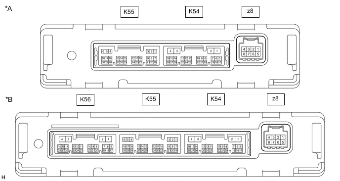
*A w/o Seat Heater *B w/ Seat Heater
-
Disconnect the K54 air conditioning amplifier assembly connector.
-
Measure the voltage and resistance according to the value(s) in the table below.
Tech Tips
Measure the values on the wire harness side with the connector disconnected.
Terminal No. (Symbol) Wiring Color Terminal Description Condition Specified Condition K54-2 (IG+) - K54-4 (GND) LA-GR - W-B Power source (IG) Ignition switch ON 11 to 14 V K54-2 (IG+) - K54-4 (GND) LA-GR - W-B Power source (IG) Ignition switch off Below 1 V K54-1 (B) - K54-4 (GND) LA-B - W-B Battery power supply Always 11 to 14 V K54-4 (GND) - Body ground W-B - Body ground Ground Always Below 1 Ω -
Reconnect the K54 air conditioning amplifier assembly connector.
-
Measure the voltage and check for pulses according to the value(s) in the table below.
Terminal No. (Symbol) Wiring Color Terminal Description Condition Specified Condition K54-5 (RDFG) - K54-4 (GND) L - W-B Rear window defogger signal Ignition switch ON, rear window defogger switch off 11 to 14 V K54-5 (RDFG) - K54-4 (GND) L - W-B Rear window defogger signal Ignition switch ON, rear window defogger switch on Below 1 V K54-14 (LIN1) - K54-4 (GND)* BE - W-B LIN communication line Ignition switch ON Pulse generation
-
*: except 8 Inch Display
-
-
-
CHECK AIR CONDITIONING CONTROL ASSEMBLY (except 8 Inch Display)

-
Disconnect the K26 air conditioning control assembly connector.
-
Measure the voltage and resistance according to the value(s) in the table below.
Tech Tips
Measure the values on the wire harness side with the connector disconnected.
Terminal No. (Symbol) Wiring Color Terminal Description Condition Specified Condition K26-2 (IG+) - K26-6 (GND) GR - W-B Power source (IG) Ignition switch ON 11 to 14 V K26-2 (IG+) - K26-6 (GND) GR - W-B Power source (IG) Ignition switch off Below 1 V K26-6 (GND) - Body ground W-B - Body ground Ground Always Below 1 Ω -
Reconnect the K26 air conditioning control assembly connector.
-
Check for pulses according to the value(s) in the table below.
Terminal No. (Symbol) Wiring Color Terminal Description Condition Specified Condition K26-9 (LIN1) - K26-6 (GND) LG - W-B LIN communication line Ignition switch ON Pulse generation
-
-
CHECK RADIO AND DISPLAY RECEIVER ASSEMBLY (for 8 Inch Display)