MULTI-MODE MANUAL TRANSAXLE SYSTEM, Diagnostic DTC:P0617
| DTC Code | DTC Name |
|---|---|
| P0617 | Starter Relay Circuit High |
DESCRIPTION
If engine speed and battery voltage are above a certain level while the vehicle is being driven (not start condition) and the STA signal is on for a certain amount of time, this DTC is stored.
DTC No. |
Detection Item |
DTC Detection Condition |
Trouble Area |
MIL |
Warning Indicate |
Memory |
|---|---|---|---|---|---|---|
P0617 |
Starter Relay Circuit High |
Following conditions (1), (2) and (3) met for 20 seconds (1-trip detection logic):
|
|
Comes on |
Comes on |
DTC stored |
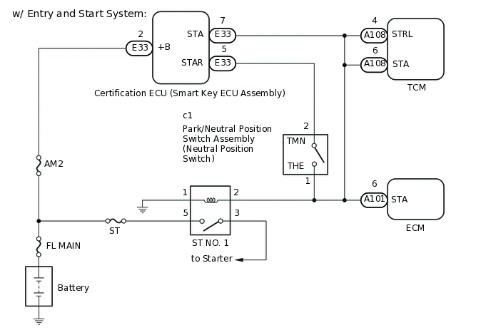
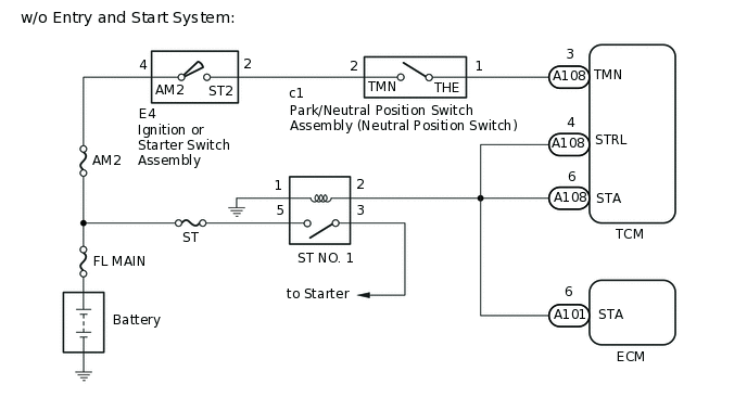
WIRING DIAGRAM
CAUTION / NOTICE / HINT
If DTC P0703 is output, troubleshoot this code first.
PROCEDURE
READ VALUE USING GTS (STA SWITCH SIGNAL)
Connect the GTS to the DLC3.
Turn the ignition switch to ON.
Turn the GTS on.
Enter the following menus: Powertrain / Multi-Mode M/T / Data List / STA Switch Signal.
According to the display on the GTS, read the Data List.
Powertrain > Multi-Mode M/T > Data List
Tester Display
Measurement Item
Range
Normal Condition
Diagnostic Note
STA Switch Signal
STA signal
OFF or ON
OFF: Not cranking
ON: Cranking
-
Powertrain > Multi-Mode M/T > Data List
Tester Display
STA Switch Signal
OK
OFF is displayed in the Data List when not cranking.
Result
Result
Proceed to
NG (w/ Entry and Start System)
A
NG (w/o Entry and Start System)
B
OK
C
INSPECT NEUTRAL POSITION SWITCH
Inspect the neutral position switch assembly.
Result
Proceed to
OK
NG
REPAIR OR REPLACE HARNESS OR CONNECTOR (STA SIGNAL CIRCUIT)
Repair or replace the harness or connector (neutral position switch - certification ECU - ST No. 1 relay - ECM - TCM).
Result
Proceed to
NEXT
CHECK WHETHER DTC OUTPUT RECURS
Connect the GTS to the DLC3.
Turn the ignition switch to ON.
Turn the GTS on.
Clear the DTCs.
Powertrain > Multi-Mode M/T > Clear DTCs
Drive the vehicle at more than 20 km/h (12.4 mph) for more than 20 seconds.
Enter the following menus: Powertrain / Multi-Mode M/T.
Powertrain > Multi-Mode M/T > Trouble Codes
Read the DTCs.
Result
Result
Proceed to
DTC P0617 is output
A
DTCs are not output
B
B END
REPLACE TCM
Replace the TCM.
for LHD:Click hereClick here
for RHD:Click hereClick here
Result
Proceed to
NEXT
PERFORM INITIALIZATION
Perform the initialization and learning procedure.
Result
Proceed to
NEXT
NEXT END
INSPECT ST NO. 1 RELAY
Remove the ST NO. 1 relay from the engine room relay block and junction block assembly.
Enter the following menus: Powertrain / Multi-Mode M/T / Data List / STA Switch Signal.
In accordance with the display on the GTS, read the Data List.
Powertrain > Multi-Mode M/T > Data List
Tester Display
Measurement Item
Range
Normal Condition
Diagnostic Note
STA Switch Signal
STA signal
OFF or ON
OFF: Not cranking
ON: Cranking
-
Powertrain > Multi-Mode M/T > Data List
Tester Display
STA Switch Signal
Result
Result
Proceed to
ON is displayed in the Data List when not cranking.
A
OFF is displayed in the Data List when not cranking.
B
B REPLACE ST NO. 1 RELAY
INSPECT ECM
Disconnect the ECM connectors.
Enter the following menus: Powertrain / Multi-Mode M/T / Data List / STA Switch Signal.
In accordance with the display on the GTS, read the Data List.
Powertrain > Multi-Mode M/T > Data List
Tester Display
Measurement Item
Range
Normal Condition
Diagnostic Note
STA Switch Signal
STA signal
OFF or ON
OFF: Not cranking
ON: Cranking
-
Powertrain > Multi-Mode M/T > Data List
Tester Display
STA Switch Signal
Result
Result
Proceed to
ON is displayed in the Data List when not cranking.
A
OFF is displayed in the Data List when not cranking.
B
CHECK HARNESS AND CONNECTOR (TCM - ST RELAY - ECM)
-
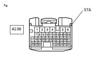
*a
Front view of wire harness connector
(to TCM)
Disconnect the TCM connector.
Measure the voltage according to the value(s) in the table below.
Standard Voltage
Tester Connection
Condition
Specified Condition
A108-6 (STA) - Body ground
Ignition switch off
Below 1 V
Result
Proceed to
OK
NG
NG REPAIR OR REPLACE HARNESS OR CONNECTOR
-
REPLACE TCM
Replace the TCM.
for LHD:Click hereClick here
for RHD:Click hereClick here
Result
Proceed to
NEXT
PERFORM INITIALIZATION
Perform the initialization and learning procedure.
Result
Proceed to
NEXT
NEXT END