FRONT LOWER SUSPENSION ARM REMOVAL
CAUTION / NOTICE / HINT
Use the same procedure for the RH and LH sides.
The procedure listed below is for the LH side.
PROCEDURE
REMOVE FRONT WHEELS
REMOVE NO. 1 ENGINE UNDER COVER (for 1ZR-FAE, 2ZR-FAE)
REMOVE NO. 1 ENGINE UNDER COVER (for 1WW)
REMOVE CENTER NO. 4 ENGINE UNDER COVER
REMOVE REAR ENGINE UNDER COVER LH
Remove the 5 clips and under cover.
REMOVE REAR ENGINE UNDER COVER RH
Tip:Perform the same procedure as for the LH side.
REMOVE NO. 2 ENGINE UNDER COVER
PLACE FRONT WHEELS FACING STRAIGHT AHEAD
SECURE STEERING WHEEL
REMOVE COLUMN HOLE COVER SILENCER SHEET
DISCONNECT NO. 2 STEERING INTERMEDIATE SHAFT ASSEMBLY
REMOVE NO. 1 STEERING COLUMN HOLE COVER SUB-ASSEMBLY
DISCONNECT FRONT STABILIZER LINK ASSEMBLY LH
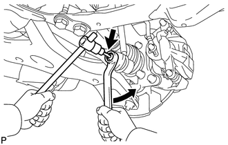
Remove the nut and disconnect the stabilizer link assembly LH from the front stabilizer bar.
Tip:If the ball joint turns together with the nut, use a 6 mm hexagon wrench to hold the stud bolt.
DISCONNECT FRONT STABILIZER LINK ASSEMBLY RH
Tip:Perform the same procedure as for the LH side.
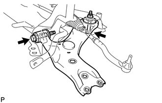
DISCONNECT TIE ROD END SUB-ASSEMBLY LH
DISCONNECT TIE ROD END SUB-ASSEMBLY RH
Tip:Perform the same procedure as for the LH side.
LOOSEN FRONT NO. 1 LOWER SUSPENSION ARM SUB-ASSEMBLY LH
-
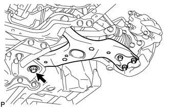
Loosen the bolt.
Note:Because the nut has its own stopper, do not turn the nut. Loosen the bolt with the nut fixed in place.
-
LOOSEN FRONT NO. 1 LOWER SUSPENSION ARM SUB-ASSEMBLY RH
Tip:Perform the same procedure as for the LH side.
DISCONNECT FRONT NO. 1 LOWER SUSPENSION ARM SUB-ASSEMBLY LH
DISCONNECT FRONT NO. 1 LOWER SUSPENSION ARM SUB-ASSEMBLY RH
Tip:Perform the same procedure as for the LH side.
REMOVE FRONT LOWER ENGINE MOUNTING BRACKET REINFORCEMENT
REMOVE FRONT SUSPENSION MEMBER REINFORCEMENT LH
-
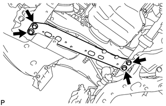
Remove the 4 bolts and front suspension member reinforcement LH.
-
REMOVE FRONT SUSPENSION MEMBER REINFORCEMENT RH
-
Remove the 4 bolts and front suspension member reinforcement RH.
-
REMOVE FRONT SUSPENSION MEMBER REAR BRACE LH
-
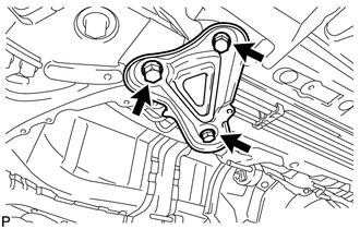
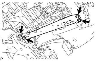
Remove the 3 bolts and front suspension member rear brace LH.
-
REMOVE FRONT SUSPENSION MEMBER REAR BRACE RH
Tip:Perform the same procedure as for the LH side.
REMOVE FRONT SUSPENSION CROSSMEMBER SUB-ASSEMBLY
-
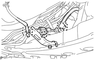
Detach the 2 clamps and claw, and disconnect the oxygen sensor wire from the front suspension crossmember.
Support the front suspension crossmember with a transmission jack.
Remove the 4 bolts, 2 nuts and front suspension crossmember.
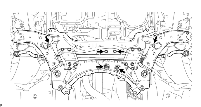
-
REMOVE FRONT NO. 1 LOWER SUSPENSION ARM SUB-ASSEMBLY LH
-
Remove the 2 bolts, nut and front lower suspension arm from the front suspension crossmember.
Note:Because the nut has its own stopper, do not turn the nut. Loosen the bolt with the nut fixed in place.
-