POWER DOOR LOCK CONTROL SYSTEM Door Control Switch Circuit
DESCRIPTION
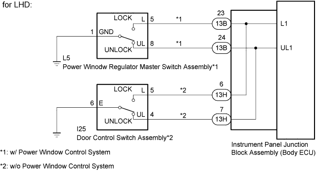
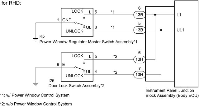
The instrument panel junction block assembly (body ECU) receivers the door lock/unlock request signal from the power window regulator master switch assembly*1 or door control switch assembly*2. The instrument panel junction block assembly (body ECU) actives the door lock motor on all door according to the signal.
-
*1: w/ Power Window Control System
-
*2: w/o Power Window Control System
WIRING DIAGRAM
INSPECTION PROCEDURE
PROCEDURE
-
CHECK VEHICLE TYPE
-
Check the vehicle type.
Result Result Proceed to w/ Power Window Control System A w/o Power Window Control System B
B 
INSPECT DOOR CONTROL SWITCH ASSEMBLY Click here
A 
-
-
INSPECT POWER WINDOW REGULATOR MASTER SWITCH ASSEMBLY (DOOR CONTROL SWITCH)
-
Remove the power window regulator master switch assembly Click here.
-
Inspect the power window regulator master switch assembly Click here.
NG 
REPLACE POWER WINDOW REGULATOR MASTER SWITCH ASSEMBLY Click here
OK
-
-
CHECK HARNESS AND CONNECTOR (INSTRUMENT PANEL JUNCTION BLOCK ASSEMBLY [BODY ECU] - POWER WINDOW REGULATOR MASTER SWITCH ASSEMBLY AND BODY GROUND)
-
Disconnect the 13B instrument panel junction block assembly (body ECU) connector.
-
Disconnect the L5*1 or K5*2 power window regulator master switch assembly connector.
-
*1: for LHD
-
*2: for RHD
-
-
Measure the resistance according to the value(s) in the table below.
Standard Resistance for LHD Tester Connection Condition Specified Condition 13B-23 (L1) - L5-5 (L) Always Below 1 Ω 13B-24 (UL1) - L5-8 (UL) Always Below 1 Ω L5-1 (GND) - Body ground Always Below 1 Ω 13B-23 (L1) or L5-5 (L) - Body ground Always 10 kΩ or higher 13B-24 (UL1) or L5-8 (UL) - Body ground Always 10 kΩ or higher for RHD Tester Connection Condition Specified Condition 13B-6 (L1) - K5-5 (L) Always Below 1 Ω 13B-5 (UL1) - K5-8 (UL) Always Below 1 Ω K5-1 (GND) - Body ground Always Below 1 Ω 13B-6 (L1) or K5-5 (L) - Body ground Always 10 kΩ or higher 13B-5 (UL1) or K5-8 (UL) - Body ground Always 10 kΩ or higher
NG
REPAIR OR REPLACE HARNESS OR CONNECTOR
OK 
PROCEED TO NEXT CIRCUIT INSPECTION SHOWN IN PROBLEM SYMPTOMS TABLE Click here
-
-
INSPECT DOOR CONTROL SWITCH ASSEMBLY
-
Remove the door control switch assembly.
-
Inspect the door control switch assembly Click here.
NG
REPLACE DOOR CONTROL SWITCH ASSEMBLY
OK
-
-
CHECK HARNESS AND CONNECTOR (INSTRUMENT PANEL JUNCTION BLOCK ASSEMBLY [BODY ECU] - DOOR CONTROL SWITCH ASSEMBLY AND BODY GROUND)
-
Disconnect the 13H instrument panel junction connector assembly (body ECU) connector.
-
Disconnect the I25 door control switch assembly connector.
-
Measure the resistance according to the value(s) in the table below.
Standard Resistance Tester Connection Condition Specified Condition 13H-6 (L1) - I25-5 (L) Always Below 1 Ω 13H-7 (UL1) - I25-4 (UL) Always Below 1 Ω I25-6 (E) - Body ground Always Below 1 Ω 13H-6 (L1) or I25-5 (L) - Body ground Always 10 kΩ or higher 13H-7 (UL1) or I25-4 (UL) - Body ground Always 10 kΩ or higher
NG
REPAIR OR REPLACE HARNESS OR CONNECTOR
OK
PROCEED TO NEXT CIRCUIT INSPECTION SHOWN IN PROBLEM SYMPTOMS TABLE Click here
-