ENGINE UNIT
-
CONSTRUCTION
-
Each cylinder of this engine has 2 intake valves and 2 exhaust valves. Intake and exhaust efficiency is increased due to the larger total port areas.
-
This engine uses a valve rocker arm sub-assembly with built-in needle bearings. This reduces the friction that occurs between the cams and the valve rocker arm sub-assembly that push the valves down, thus improving fuel economy.
-
A valve lash adjuster assembly, which maintains a constant 0 valve clearance through the use of oil pressure and spring force, is used.
-
The exhaust camshaft is driven by a timing chain (chain sub-assembly), while the intake camshaft is driven through a gear on the exhaust camshaft.
-
A supply pump assembly is driven by the exhaust camshaft to achieve a lightweight and compact design.
-
A vacuum pump assembly is driven by the intake camshaft to achieve a lightweight and compact design.
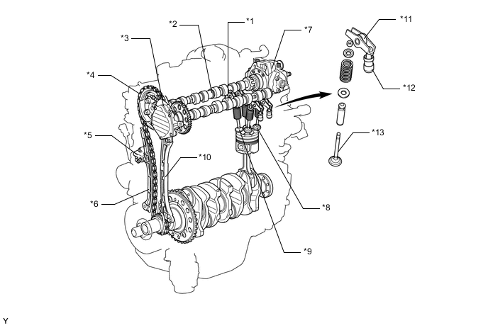
*1 Intake Camshaft *2 Exhaust Camshaft *3 Vacuum Pump Assembly *4 Timing Chain (Chain Sub-assembly) *5 No. 1 Chain Tensioner Assembly *6 Chain Tensioner Slipper *7 Supply Pump Assembly *8 Intake Valve *9 Exhaust Valve *10 No. 1 Chain Vibration Damper *11 Valve Rocker Arm Sub-assembly *12 Valve Lash Adjuster Assembly *13 Valve - - 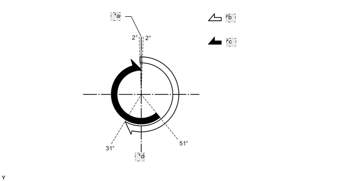
*a TDC *b Intake valve opening angle *c Exhaust valve opening angle *d BDC
-