POWER WINDOW REGULATOR MOTOR(for Front Door) INSPECTION
PROCEDURE
INSPECT POWER WINDOW REGULATOR MOTOR ASSEMBLY LH
w/ Jam Protection Function:
-
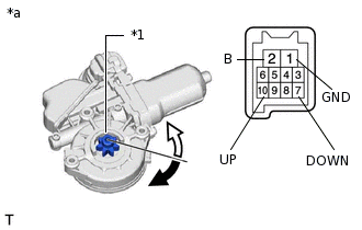
*1
Motor Gear
*a
Component without harness connected
(Power Window Regulator Motor Assembly LH)

Clockwise

Counterclockwise
Apply positive (+) battery voltage to the connector terminal 2 (B).
Apply negative (-) battery voltage to the connector terminals 1 (GND) and 7 (DOWN) / 10 (UP).
Note:Do not apply voltage to any terminals except terminals 1 and 2, to avoid damaging the pulse sensor inside the motor.
Reset the power window regulator motor (initialize the pulse sensor) after installing the power window regulator motor and regulator assembly to the door.
Check that the motor gear rotates smoothly as follows.
OK
Measurement Condition
Specified Condition
Battery positive (+) → 2 (B)
Battery negative (-): 1 (GND) (3 seconds or more) → 1 (GND) and 10 (UP) (within 1 second) → 1 (GND) (within 1 second) → 1 (GND) and 10 (UP)
Motor gear rotates clockwise (UP)
Battery positive (+) → 2 (B)
Battery negative (-): 1 (GND) (3 seconds or more) → 1 (GND) and 7 (DOWN) (within 1 second) → 1 (GND) (within 1 second) → 1 (GND) and 7 (DOWN)
Motor gear rotates counterclockwise (DOWN)
-
w/o Jam Protection Function:
-
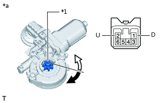
*1
Motor Gear
*a
Component without harness connected
(Power Window Regulator Motor Assembly LH)
Clockwise
Counterclockwise
Apply battery voltage to connector terminals 1 (D) and 2 (U).
Note:Do not apply battery voltage to any terminals except terminals 1 (D) and 2 (U).
-
Check that the motor gear rotates smoothly as follows.
OK
Measurement Condition
Specified Condition
Battery positive (+) → 2 (U)
Battery negative (-) → 1 (D)
Motor gear rotates clockwise
Battery positive (+) → 1 (D)
Battery negative (-) → 2 (U)
Motor gear rotates counterclockwise
If the result is not as specified, replace the power window regulator motor assembly LH.
INSPECT POWER WINDOW REGULATOR MOTOR ASSEMBLY RH
w/ Jam Protection Function:
-
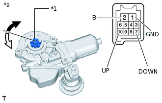
*1
Motor Gear
*a
Component without harness connected
(Power Window Regulator Motor Assembly LH)
Clockwise
Counterclockwise
Apply positive (+) battery voltage to the connector terminal 2 (B).
Apply negative (-) battery voltage to the connector terminals 1 (GND) and 7 (DOWN) / 10 (UP).
Note:Do not apply voltage to any terminals except terminals 1 and 2, to avoid damaging the pulse sensor inside the motor.
Reset the power window regulator motor (initialize the pulse sensor) after installing the power window regulator motor and regulator assembly to the door.
Check that the motor gear rotates smoothly as follows.
OK
Measurement Condition
Specified Condition
Battery positive (+) → 2 (B)
Battery negative (-): 1 (GND) (3 seconds or more) → 1 (GND) and 10 (UP) (within 1 second) → 1 (GND) (within 1 second) → 1 (GND) and 10 (UP)
Motor gear rotates clockwise (UP)
Battery positive (+) → 2 (B)
Battery negative (-): 1 (GND) (3 seconds or more) → 1 (GND) and 7 (DOWN) (within 1 second) → 1 (GND) (within 1 second) → 1 (GND) and 7 (DOWN)
Motor gear rotates counterclockwise (DOWN)
-
w/o Jam Protection Function:
-
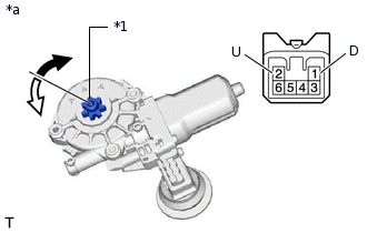
*1
Motor Gear
*a
Component without harness connected
(Power Window Regulator Motor Assembly RH)
Clockwise
Counterclockwise
Apply battery voltage to connector terminals 1 (D) and 2 (U).
Note:Do not apply battery voltage to any terminals except terminals 1 (D) and 2 (U).
Check that the motor gear rotates smoothly as follows
OK
Measurement Condition
Specified Condition
Battery positive (+) → 1 (D)
Battery negative (-) → 2 (U)
Motor gear rotates clockwise
Battery positive (+) → 2 (U)
Battery negative (-) → 1 (D)
Motor gear rotates counterclockwise
If the result is not as specified, replace the power window regulator motor assembly RH.
-