FRONT SIDE MEMBER ASSEMBLY REPLACEMENT
-
With the front fender apron assembly removed.
-
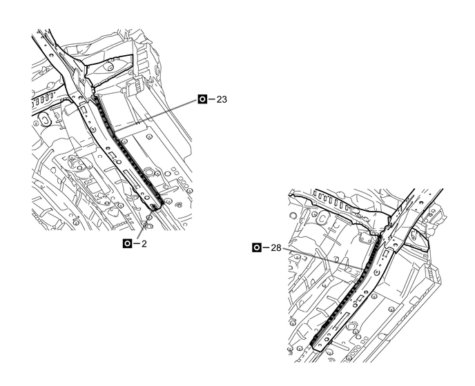
REMOVAL
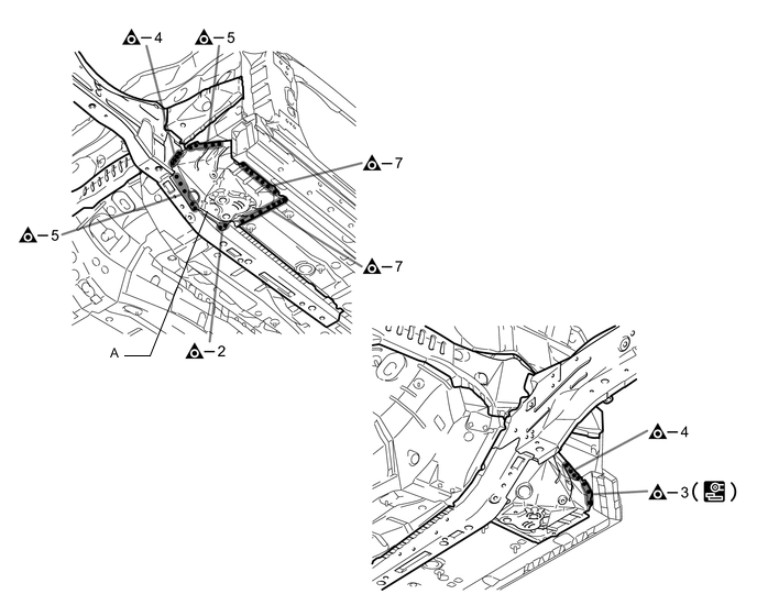
Symbol Meaning 
Remove Weld Points 
Remove Weld Points 
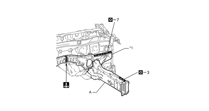
Cut with Disc Sander etc. 
Cut and Join Location
-
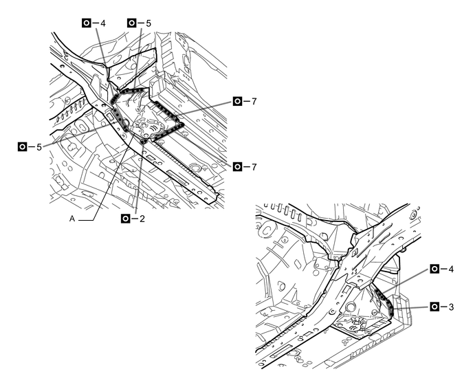
Remove the A.
-
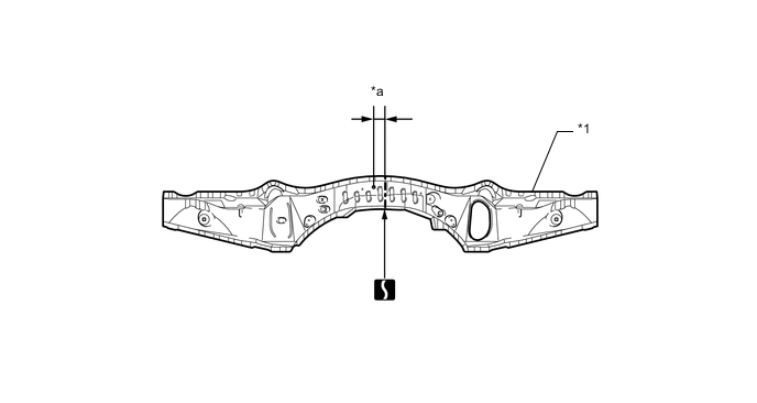
Remove the front side member sub-assembly and floor crossmember sub-assembly No.3.
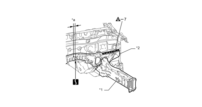
*1 FRONT SIDE MEMBER SUB-ASSEMBLY *2 FLOOR CROSSMENBER SUB-ASSEMBLY NO.3 *a 35 mm (1.38 in.) - - 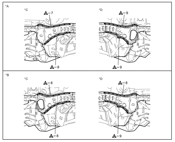
*A for LHD *B for RHD *C RH Side *D LH Side 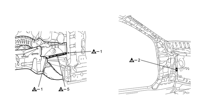

-
-
INSTALLATION
Symbol Meaning Remove Weld Points 
Plug Weld 
Plug Weld Cut and Join Location 
Butt Weld
-
Temporarily install the new parts and measure each part of the new parts in accordance with the body dimension diagram. (See the body dimensions)
-
Make sure to attach correctly in accordance with the body dimension diagram as this part affects the front wheel alignment.
-
If the entire supply part is not needed, remove the part of the supply part that is needed.
*1 FLOOR CROSSMENBER SUB-ASSEMBLY NO.3 - - *a 35 mm (1.38 in.) - - -
Remove A and B from a new front side member sub-assembly.
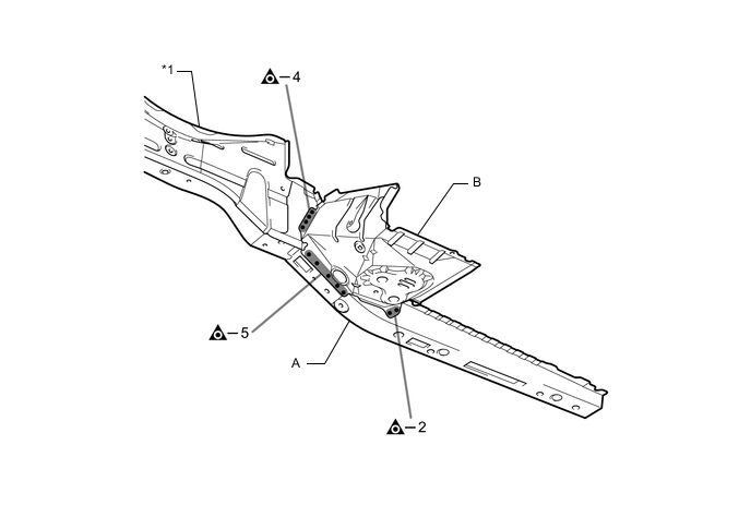
*1 FRONT SIDE MEMBER SUB-ASSEMBLY - - -
Before temporarily installing the new parts, weld the floor crossmember sub-assembly No.3 and A with the standardnumber of welding points.
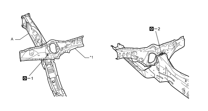
*1 FLOOR CROSSMENBER SUB-ASSEMBLY NO.3 - - 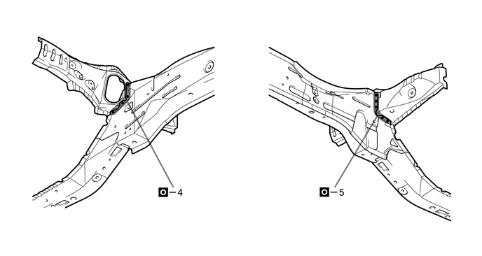
-
Weld the floor crossmember sub-assembly No.3 and A to the vehicle side.
*1 FLOOR CROSSMENBER SUB-ASSEMBLY NO.3 - - 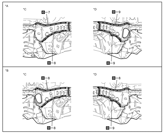
*A for LHD *B for RHD *C RH Side *D LH Side 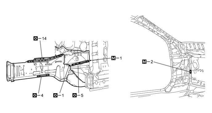
-
Weld the A to the vehicle side.
-
After welding, apply body sealer and undercoating to the corresponding parts. (See the painting /coating)
-
After applying the top coat, apply anti-rust agent to the internal panel portion of the closed section structural weld points.
-