AUTOMATIC TRANSMISSION SYSTEM (for 2KD-FTV), Diagnostic DTC:P0500
| DTC Code | DTC Name |
|---|---|
| P0500 | Vehicle Speed Sensor Malfunction |
DESCRIPTION
The vehicle speed sensor (SPD1) outputs a 4-pulse signal for every revolution of the rotor shaft, which is rotated by the transmission output shaft via the driven gear. After this signal is converted into a more precise rectangular waveform by the waveform shaping circuit inside the combination meter, it is then transmitted to the TCM. The TCM determines the vehicle speed based on the frequency of these pulse signals.
| DTC Code | DTC Detection Condition | Trouble Area |
|---|---|---|
| P0500 | All conditions below are detected 500 times or more continuously (2-trip detection logic): (a) No signal from vehicle speed sensor (SPD1) is input to TCM while 48 pulses of speed sensor (SP2) signal are sent (b) Vehicle speed is 9 km/h (6 mph) or more for at least 4 seconds (c) PNP switch is off (shift lever not in P or N) |
|
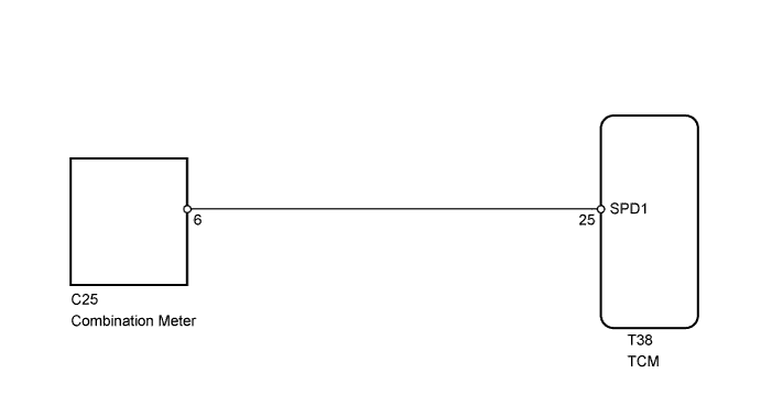
WIRING DIAGRAM
INSPECTION PROCEDURE
Tech Tips
Read freeze frame data using the intelligent tester. Freeze frame data records the engine conditions when a malfunction is detected. When troubleshooting, freeze frame data can help determine if the vehicle was moving or stationary, if the engine was warmed up or not, and other data from the time the malfunction occurred.
PROCEDURE
-
READ VALUE USING INTELLIGENT TESTER (VEHICLE SPEED)
-
Connect the intelligent tester to the DLC3.
-
Turn the ignition switch to ON.
-
Turn the intelligent tester on.
-
Enter the following menus: Powertrain / ECT / Data List.
-
Drive the vehicle.
-
Read the value displayed on the tester.
ECT Tester Display Measurement Item/Range Normal Condition Diagnostic Note Vehicle Speed Vehicle speed/
Min.: 0 km/h (0 mph)
Max.: 255 km/h (158 mph)
Actual vehicle speed Speed indicated on speedometer OK Vehicle speed displayed on tester and speedometer display are equal.
NG 
CHECK COMBINATION METER ASSEMBLY (SPD1 SIGNAL WAVEFORM) Click here
OK 
CHECK FOR INTERMITTENT PROBLEMS
-
-
CHECK COMBINATION METER ASSEMBLY (SPD1 SIGNAL WAVEFORM)
-
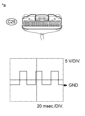
Text in Illustration *a Component with harness connected
(Combination Meter Assembly)
Remove the combination meter assembly with the connector(s) still connected.
-
Move the shift lever to N.
-
Jack up the vehicle.
-
Turn the ignition switch to ON.
-
Check the signal waveform according to the condition(s) in the table below.
Measurement Condition Terminal No. (Symbol) Tool Setting Condition C25-6 - Body ground 5 V/DIV., 20 msec./DIV. Vehicle speed 20 km/h (12 mph) OK The waveform is displayed as shown in the illustration.
NG 
GO TO METER / GAUGE SYSTEM (SPEEDOMETER MALFUNCTION) Click here
OK 
-
-
CHECK HARNESS AND CONNECTOR (COMBINATION METER ASSEMBLY - TCM)
-
Disconnect the C25 combination meter assembly connector.
-
Disconnect the T38 TCM connector.
-
Measure the resistance according to the value(s) in the table below.
Standard Resistance Tester Connection Condition Specified Condition C25-6 - T38-25 (SPD1) Always Below 1 Ω C25-6 or T38-25 (SPD1) - Body ground Always 10 kΩ or higher
NG
REPAIR OR REPLACE HARNESS OR CONNECTOR
OK
REPLACE TCM
-