AUDIO AND VISUAL SYSTEM(for Radio and Display Type), Diagnostic DTC:B157D
| DTC Code | DTC Name |
|---|---|
| B157D | DAB Tuner Antenna Disconnected |
DESCRIPTION
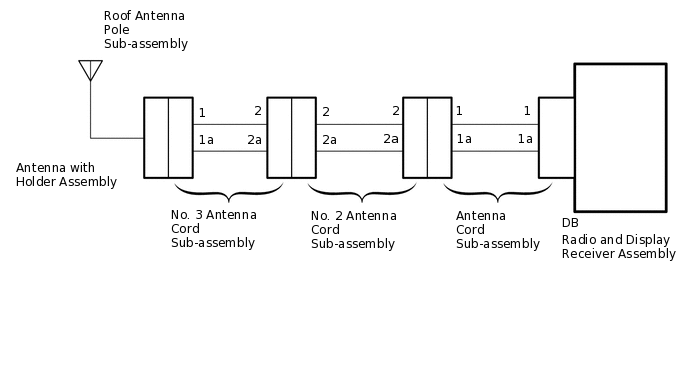
This DTC is stored when a malfunction occurs in the digital audio broadcasting antenna cable which is connected to the radio and display receiver assembly.
DTC No. |
Detection Item |
DTC Detection Condition |
Trouble Area |
|---|---|---|---|
B157D |
DAB Tuner Antenna Disconnected |
The digital audio broadcasting antenna cable is not connected. |
|
WIRING DIAGRAM
PROCEDURE
CHECK CONNECTION OF DAB RADIO ANTENNA CABLE
Check if the DAB radio antenna cable is securely connected to the radio and display receiver assembly.
OK
DAB radio antenna cable is securely connected
Result
Proceed to
OK
NG
NG SECURELY CONNECT DAB RADIO ANTENNA CABLE
CHECK ANTENNA CORD SUB-ASSEMBLY
-
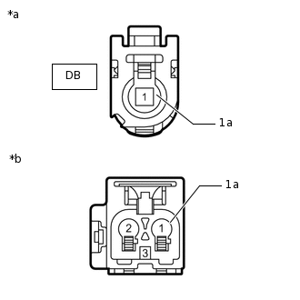
*a
Front view of wire harness connector
(to Radio and Display Receiver Assembly)
*b
Front view of wire harness connector
(to No. 2 Antenna Cord Sub-assembly)
Remove the antenna connector from the radio and display receiver assembly.
Remove the antenna connector from the No. 2 antenna cord sub-assembly.
Measure the resistance according to the value(s) in the table below.
Standard Resistance
Tester Connection
Condition
Specified Condition
DB-1 - 1
Always
Below 1 Ω
DB-1a - 1a
Always
Below 1 Ω
DB-1 - Body ground
Always
10 kΩ or higher
DB-1a - Body ground
Always
10 kΩ or higher
Result
Proceed to
OK
NG
-
CHECK NO. 2 ANTENNA CORD SUB-ASSEMBLY
-
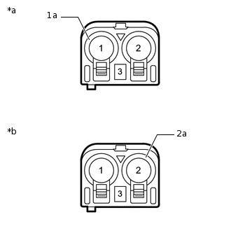
*a
Front view of wire harness connector
(to Antenna Cord Sub-assembly)
*b
Front view of wire harness connector
(to No. 3 Antenna Cord Sub-assembly)
Remove the antenna connector from the antenna cord sub-assembly.
Remove the antenna connector from the No. 3 antenna cord sub-assembly.
Measure the resistance according to the value(s) in the table below.
Standard Resistance
Tester Connection
Condition
Specified Condition
1 - 2
Always
Below 1 Ω
1a - 2a
Always
Below 1 Ω
1 - Body ground
Always
10 kΩ or higher
1a - Body ground
Always
10 kΩ or higher
Result
Proceed to
OK
NG
-
CHECK NO. 3 ANTENNA CORD SUB-ASSEMBLY
-
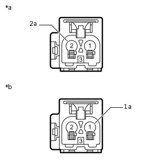
*a
Front view of wire harness connector
(to No. 2 Antenna Cord Sub-assembly)
*b
Front view of wire harness connector
(to Antenna with Holder Assembly)
Remove the antenna connector from the No. 2 antenna cord sub-assembly.
Remove the antenna connector from the antenna with holder assembly.
Measure the resistance according to the value(s) in the table below.
Standard Resistance
Tester Connection
Condition
Specified Condition
2 - 1
Always
Below 1 Ω
2a - 1a
Always
Below 1 Ω
2 - Body ground
Always
10 kΩ or higher
2a - Body ground
Always
10 kΩ or higher
Result
Proceed to
OK
NG
-
CHECK ROOF ANTENNA POLE SUB-ASSEMBLY
Check that the roof antenna pole sub-assembly is securely installed.
OK
The roof antenna pole sub-assembly is installed properly
Result
Proceed to
OK
NG
CHECK ROOF ANTENNA POLE SUB-ASSEMBLY
Replace the roof antenna pole sub-assembly with a known good one.
Clear the DTCs.
Body Electrical > Navigation System > Clear DTCs
Check for DTCs.
Body Electrical > Navigation System > Trouble Codes
OK
No DTCs are output.
Result
Proceed to
OK
NG
OK END (ROOF ANTENNA POLE SUB-ASSEMBLY IS DEFECTIVE)
CHECK ANTENNA WITH AMPLIFIER ASSEMBLY
Replace the antenna with holder assembly with a known good one.
Clear the DTCs.
Body Electrical > Navigation System > Clear DTCs
Check for DTCs.
Body Electrical > Navigation System > Trouble Codes
OK
No DTCs are output.
Result
Proceed to
OK
NG
OK END (ANTENNA WITH HOLDER ASSEMBLY IS DEFECTIVE)