AIR CONDITIONING SYSTEM
-
OUTLINE
-
Air Conditioning System
-
An automatic air conditioning system or a manual air conditioning system is provided depending on the model.
-
The automatic air conditioning system uses left and right independent temperature control to enhance comfort.
-
-
Combustion Type Power Heater
-
Depending on the operating condition, the engine coolant temperature remains low, making it difficult to ensure the proper heating effect. Thus, in order to provide an adequate heating effect, a combustion type power heater (heater and accessory assembly) is provided depending on the model.
-
A heater switch assembly is located in the No. 2 instrument panel lower finish panel.
-
-
-
SPECIFICATIONS
-
Ventilation and Heater Core
Model Specifications Heater Radiator Unit Sub-assembly Type Straight Flow Aluminum-II (SFA-II) Size (W x H x L) 201.5 mm x 150 mm x 27 mm
(7.93 in. x 5.90 in. x 1.06 in.)
Fin Pitch 1.8 mm (0.07 in.) Blower with Fan Motor Assembly Motor Type K70-10.5T*1
K70-10T*2
Fan Type Semi Sirocco Fan Size (Dia. x H) 155 mm x 65 mm (6.10 in. x 2.56 in.)
-
*1: Models with manual air conditioning system
-
*2: Models with automatic air conditioning system
-
-
Air Conditioning
Model Specifications Cooler Condenser Assembly Type Multi-Flow-IV (MF-IV) Sub-cool Size (W x H x L) 680 mm x 415 mm x 16 mm
(26.8 in. x 16.3 in. x 0.63 in.)
Fin Pitch 2.75 mm (0.11 in.) Cooler Compressor Assembly 7SES17 (DL Pulley)*1
6SES14 (DL Pulley)*2
7SAS17*3
No. 1 Cooler Evaporator Sub-assembly Motor Type Revolutionary Super-slim Structure (RS) Size (W x H x L) 226.1 mm x 241 mm x 38 mm
(8.90 in. x 9.49 in. x 1.50 in.)
Fin Pitch 3.0 mm (0.11 in.) Refrigerant Type HFC-134a Charge Volume 470 g to 530 g (16.6 oz. to 18.7 oz.)
-
*1: Models with 2AR-FE or 3ZR-FE engine
-
*2: Models with 3ZR-FAE, 2AD-FHV, 2AD-DPF, 2AD-CCO or 2WW engine
-
*3: 2WD Models for Korea
-
-
-
MAIN FEATURES
-
The air conditioning system has the following features:
High Performance
-
The neural network control is used so passengers can finely control the air conditioning for maximum comfort.*1
-
A pollen-removal type clean air filter, which has a pollen-removal effect, is used.
-
The manual blower control has 7 steps and automatic blower control has 31 steps to allow precise control.*1
-
The blower control has 4 steps.*2
-
On models with Positive Temperature Coefficient (PTC) heater system, the system contains a PTC heater (quick heater assembly) that heats the air that has passed through the heater radiator unit sub-assembly to ensure proper heater performance.
-
A sub-cool accelerator type tube is used depending on model to ensure cooling performance.
Lightweight*1
-
A bus connector with a built-in IC is used in a lightweight wire harness design to allow a reduced number of wires.
-
The use of this connector means that pulse pattern type servo motors can be used.
Compact A blower motor with a built-in blower motor controller is used to achieve a compact construction.*1 Others The following parts are used to ensure high cooling performance while achieving a compact and lightweight construction:
-
Semi-center Location Air Conditioning Unit
-
Revolutionary Super-slim Structure (RS) Evaporator
-
Straight Flow Aluminum-II (SFA-II) Heater Radiator
-
Multi-Flow-IV (MF-IV) Sub-cool Condenser
-
*1: Models with automatic air conditioning system
-
*2: Models with manual air conditioning system
-
-
Combustion Type Power Heater
-
This heater system provides a combustion type power heater (heater and accessory assembly) between the engine and the heater radiator unit sub-assembly. Air and fuel are introduced into the heater's combustion chamber, and a glow plug is used to ignite this mixture. By heating the engine coolant that flows around the combustion chamber, this system ensures the heating effect. The system can be activated or deactivated by turning on or off the heater switch assembly provided on the No. 2 instrument panel lower finish panel.
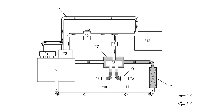
*1 Fuel Return Pipe *2 Common Rail *3 Supply Pump *4 Engine *5 Fuel Sedimenter *6 Fuel Pump *7 Combustion Type Power Heater (Heater and Accessory Assembly) *8 Combustion Chamber *9 Muffler *10 Intake Pipe *11 Exhaust Pipe *12 Fuel Tank *13 Heater Core (Radiator Heater Unit Sub-assembly) - - *a Intake Air *b Exhaust Gas *c Fuel Flow *d Engine Coolant Flow
-
-
-
PRECAUTION
-
Ignition Switch Expressions
-
The type of ignition switch used on this model differs depending on the specifications of the vehicle. The expressions listed in the table below are used in this section.
Expression Ignition Switch
(Position)
Engine Switch
(Condition)
Ignition Switch off LOCK Off (Lock) Ignition Switch ACC ACC On (ACC) Ignition Switch ON ON On (IG) Engine Start START On (Start)
-
-