LIGHTING SYSTEM Parking Brake Switch Circuit
| DTC Code | DTC Name |
|---|---|
| Parking Brake Switch Circuit |
DESCRIPTION
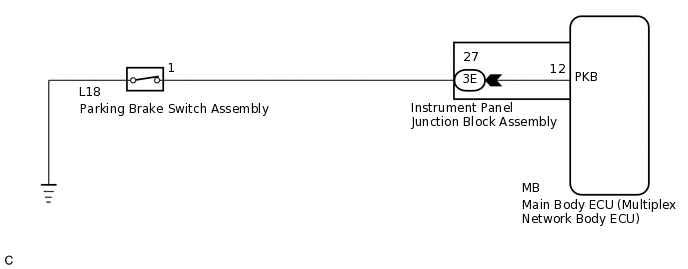
The main body ECU (multiplex network body ECU) detects the condition of the parking brake switch assembly.
WIRING DIAGRAM
PROCEDURE
READ VALUE USING GTS
Connect the GTS to the DLC3.
Turn the ignition switch to ON.
Turn the GTS on.
Enter the following menus: Body Electrical / Main Body / Data List.
Read the display on the GTS.
Body Electrical > Main Body > Data List
Tester Display
Measurement Item
Range
Normal Condition
Diagnostic Note
Parking Brake SW
Parking brake switch signal
ON or OFF
ON: Parking brake switch on
OFF: Parking brake switch off
-
Body Electrical > Main Body > Data List
Tester Display
Parking Brake SW
OK
Normal conditions listed above are displayed.
Result
Proceed to
OK
NG
OK PROCEED TO NEXT SUSPECTED AREA SHOWN IN PROBLEM SYMPTOMS TABLE
INSPECT PARKING BRAKE SWITCH ASSEMBLY
Remove the parking brake switch assembly.
Inspect the parking brake switch assembly.
Result
Proceed to
OK
NG
CHECK HARNESS AND CONNECTOR (PARKING BRAKE SWITCH ASSEMBLY - INSTRUMENT PANEL JUNCTION BLOCK ASSEMBLY)
Disconnect the 3E instrument panel junction block assembly connector.
Measure the resistance according to the value(s) in the table below.
Standard Resistance
Tester Connection
Condition
Specified Condition
L18-1 - 3E-27
Always
Below 1 Ω
L18-1 - Body ground
Always
10 kΩ or higher
Result
Proceed to
OK
NG
NG REPAIR OR REPLACE HARNESS OR CONNECTOR
INSPECT INSTRUMENT PANEL JUNCTION BLOCK ASSEMBLY
Remove the instrument panel junction block assembly.
for LHD:Click hereClick here
for RHD:Click hereClick here
Remove the main body ECU (multiplex network body ECU) from the instrument panel junction block assembly.
Measure the resistance according to the value(s) in the table below.
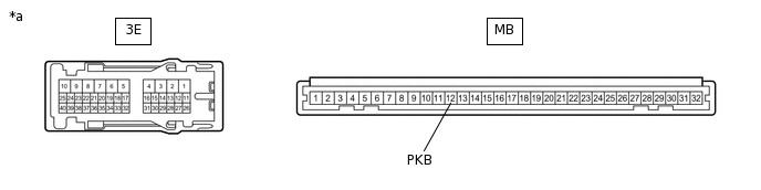
*a
Component without harness connected
(Instrument Panel Junction Block Assembly)
-
-
Standard Resistance
Tester Connection
Condition
Specified Condition
3E-27 - MB-12 (PKB)
Always
Below 1 Ω
3E-27 - Body ground
Always
10 kΩ or higher
Result
Proceed to
OK
NG
OK REPLACE MAIN BODY ECU (MULTIPLEX NETWORK BODY ECU)
for LHD:Click hereClick here
for RHD:Click hereClick here
NG REPLACE INSTRUMENT PANEL JUNCTION BLOCK ASSEMBLY
for LHD:Click hereClick here
for RHD:Click hereClick here