ENGINE IMMOBILISER SYSTEM(w/o Entry and Start System) ECU Power Source Circuit
| DTC Code | DTC Name |
|---|---|
| ECU Power Source Circuit |
DESCRIPTION
This circuit provides power to operate the transponder key ECU.
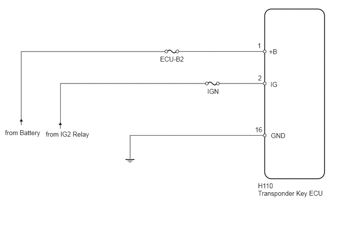
WIRING DIAGRAM
CAUTION / NOTICE / HINT
Inspect the fuses for circuits related to this system before performing the following inspection procedure.
PROCEDURE
CHECK HARNESS AND CONNECTOR (TRANSPONDER KEY ECU - BATTERY AND BODY GROUND)
-
Disconnect the H110 ECU connector.
Measure the voltage according to the value(s) in the table below.
Standard Voltage
Tester Connection
Switch Condition
Specified Condition
H110-1 (+B) - Body ground
Always
11 to 14 V
H110-2 (IG) - Body ground
Ignition switch off
Below 1 V
Ignition switch ON
11 to 14 V
Measure the resistance according to the value(s) in the table below.
Standard Resistance
Tester Connection
Condition
Specified Condition
H110-16 (GND) - Body ground
Always
Below 1 Ω
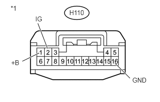
Table 1. Text in Illustration *1
Front view of wire harness connector
(to Transponder Key ECU)
REPAIR OR REPLACE HARNESS OR CONNECTOR
-