AUTOMATIC TRANSAXLE SYSTEM Transmission Control Switch Circuit
| DTC Code | DTC Name |
|---|---|
| Transmission Control Switch Circuit |
DESCRIPTION
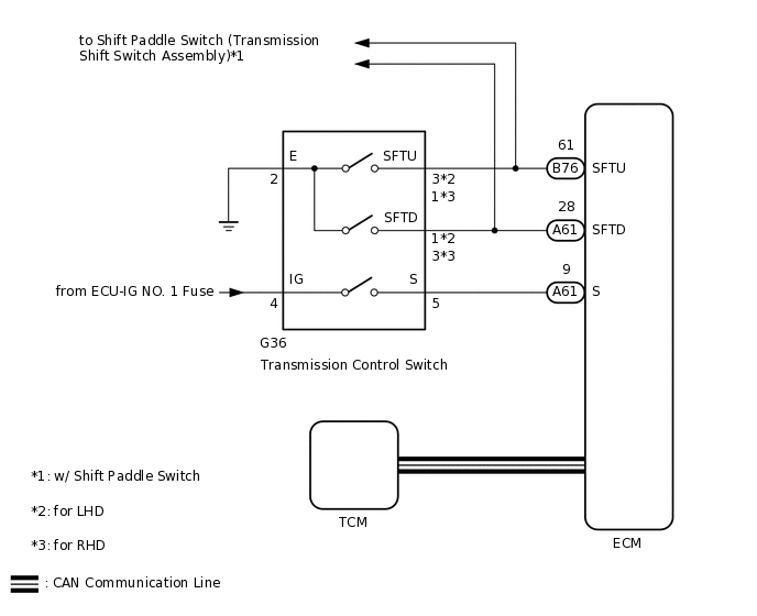
After moving the shift lever to M, it is possible to switch the shift range between "1" (M1 range) and "6" (M6 range) using the transmission control switch.
Moving the shift lever to "+" once raises the shift range by one, and moving the shift lever to "-" once lowers the shift range by one.
WIRING DIAGRAM
CAUTION / NOTICE / HINT
Inspect the fuses for circuits related to this system before performing the following procedure.
Refer to the inspection procedure for the CAN communication system.
If the CAN communication malfunctions, the TCM cannot receive current data from the ECM. In this case, the freeze frame data output from the TCM has not been updated, so the data will not be useful for the inspection. However, reading the Data List as the first step in troubleshooting is an effective way to find malfunctions.
The malfunctioning area can be confirmed using the Bus Check function of the GTS.
for LHD:
Click hereClick hereClick here
for RHD:
PROCEDURE
CHECK HARNESS AND CONNECTOR (BATTERY - TRANSMISSION CONTROL SWITCH)
-
*a
Front view of wire harness connector
(to Transmission Control Switch)
Disconnect the transmission control switch connector.
Measure the voltage according to the value(s) in the table below.
Standard Voltage
Tester Condition
Switch Condition
Specified Condition
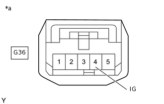
G36-4 (IG) - Body ground
Ignition switch ON
11 to 14 V
G36-4 (IG) - Body ground
Ignition switch off
Below 1 V
Result
Proceed to
OK
NG
NG CHECK POWER SOURCE CIRCUIT
-
CHECK HARNESS AND CONNECTOR (TRANSMISSION CONTROL SWITCH - BODY GROUND)
Disconnect the transmission control switch connector.
-
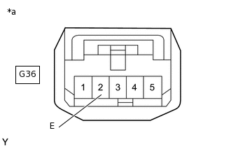
*a
Front view of wire harness connector
(to Transmission Control Switch)
Measure the resistance according to the value(s) in the table below.
Standard Resistance
Tester Connection
Condition
Specified Condition
G36-2 (E) - Body ground
Always
Below 1 Ω
Result
Proceed to
OK
NG
NG REPAIR OR REPLACE HARNESS OR CONNECTOR
INSPECT TRANSMISSION CONTROL SWITCH (TRANSMISSION FLOOR SHIFT ASSEMBLY)
Disconnect the transmission control switch connector.
-
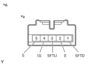
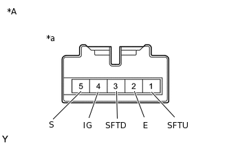
*A
for LHD
*a
Component without harness connected
(Transmission Control Switch)
for LHD:
Measure the resistance according to the value(s) in the table below.
Standard Resistance
Tester Connection
Condition
Specified Condition
4 (IG) - 5 (S)
Shift lever in M, "+" or "-"
Below 1 Ω
3 (SFTU) - 2 (E)
Shift lever held in "+" (Up-shift)
Below 1 Ω
1 (SFTD) - 2 (E)
Shift lever held in "-" (Down-shift)
Below 1 Ω
4 (IG) - 5 (S)
Shift lever not in M, "+" or "-"
10 kΩ or higher
3 (SFTU) - 2 (E)
Shift lever in M
10 kΩ or higher
1 (SFTD) - 2 (E)
Shift lever in M
10 kΩ or higher
-
*A
for RHD
*a
Component without harness connected
(Transmission Control Switch)
for RHD:
Measure the resistance according to the value(s) in the table below.
Standard Resistance
Tester Connection
Condition
Specified Condition
4 (IG) - 5 (S)
Shift lever in M, "+" or "-"
Below 1 Ω
1 (SFTU) - 2 (E)
Shift lever held in "+" (Up-shift)
Below 1 Ω
3 (SFTD) - 2 (E)
Shift lever held in "-" (Down-shift)
Below 1 Ω
4 (IG) - 5 (S)
Shift lever not in M, "+" or "-"
10 kΩ or higher
1 (SFTU) - 2 (E)
Shift lever in M
10 kΩ or higher
3 (SFTD) - 2 (E)
Shift lever in M
10 kΩ or higher
Result
Proceed to
OK
NG
CHECK HARNESS AND CONNECTOR (TRANSMISSION CONTROL SWITCH - ECM)
-
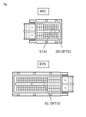
*a
Front view of wire harness connector
(to ECM)
Disconnect the ECM connector.
Turn the ignition switch to ON.
Measure the voltage according to the value(s) in the table below.
Standard Voltage
Tester Connection
Condition
Specified Condition
A61-9 (S) - Body ground
Ignition switch ON
Shift lever in M, "+" or "-"
11 to 14 V
A61-9 (S) - Body ground
Ignition switch ON
Shift lever not in M, "+" or "-"
Below 1 V
Turn the ignition switch off.
Measure the resistance according to the value(s) in the table below.
Standard Resistance
Tester Connection
Condition
Specified Condition
B76-61 (SFTU) - Body ground
Shift lever held in "+" (Up-shift)
Below 1 Ω
A61-28 (SFTD) - Body ground
Shift lever held in "-" (Down-shift)
Below 1 Ω
B76-61 (SFTU) - Body ground
Shift lever in M
10 kΩ or higher
A61-28 (SFTD) - Body ground
Shift lever in M
10 kΩ or higher
Result
Proceed to
OK
NG
NG REPAIR OR REPLACE HARNESS OR CONNECTOR
-