ENGINE ASSEMBLY INSTALLATION

PROCEDURE
-
INSTALL FRONT ENGINE MOUNTING BRACKET
-
Install the 2 front engine mounting brackets with the 4 bolts.
- Torque:
- 35 N*m { 357 kgf*cm, 26 ft.*lbf }
-
-
REMOVE ENGINE STAND
-
Attach an engine sling device and hang the engine with a chain block.
Note
With the exception of installing the engine assembly to an engine stand or removing the engine assembly from an engine stand, do not perform any work on the engine while it is suspended, as doing so is dangerous.
-
Remove the engine stand from the engine.
-
-
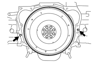
INSTALL NO. 1 CRANKSHAFT POSITION SENSOR PLATE
-
INSTALL FLYWHEEL SUB-ASSEMBLY (for Manual Transmission)
-
INSTALL CLUTCH DISC ASSEMBLY (for Manual Transmission)
-
INSTALL CLUTCH COVER ASSEMBLY (for Manual Transmission)
-
INSTALL DRIVE PLATE AND RING GEAR SUB-ASSEMBLY (for Automatic Transmission)
-
INSTALL ENGINE ASSEMBLY
-
Confirm that 2 knock pins are on the transmission contact surface of the engine block before transmission installation.
-
Keeping the engine assembly and the transmission assembly in a horizontal position, align the knock pins with each hole on the transmission assembly and install the bolt.
- Torque:
- 50 N*m { 510 kgf*cm, 37 ft.*lbf }
-
-
REMOVE ENGINE HANGER
-
CONNECT FUEL HOSE
-
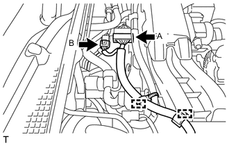
for Clamp Type:
-
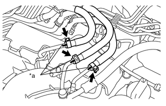
Text in Illustration *a Matchmark Connect the fuel tube and No. 2 fuel tube and fuel tube to the fuel pipe.
- Torque:
- 1.3 N*m { 13 kgf*cm, 12 in.*lbf }
Note
Align the matchmarks on the fuel hoses and fuel pipes.
-
-
for Metal Type:
-
Connect the fuel tube and No. 2 fuel tube to the fuel pipe Click here.
-
Connect the No. 2 fuel vapor feed hose to the fuel pipe.
-
-
-
INSTALL DRIVE PLATE SETTING HEXAGON BOLT (for Automatic Transmission)
-
INSTALL FLYWHEEL HOUSING UNDER COVER
-
INSTALL FRONT CROSS MEMBER SUB-ASSEMBLY
-
Install the front suspension crossmember sub-assembly with the 2 nuts.
- Torque:
- 45 N*m { 459 kgf*cm, 33 ft.*lbf }
-
-
INSTALL MANUAL TRANSMISSION ASSEMBLY (for Manual Transmission)
-
Install the 3 bolts and 2nuts.
- Torque:
- 50 N*m { 510 kgf*cm, 37 ft.*lbf }
-
-
INSTALL AUTOMATIC TRANSMISSION ASSEMBLY (for Automatic Transmission)
-
Install the 3 bolts and 2nuts.
- Torque:
- 50 N*m { 510 kgf*cm, 37 ft.*lbf }
-
-
INSTALL FRONT STABILIZER BAR (for Automatic Transmission)
-
INSTALL ENGINE UNDER COVER REAR LH (w/ Floor Under Cover)
-
Install the rear engine under cover LH with the 3 bolts and 8 clips.
- Torque:
- 7.5 N*m { 76 kgf*cm, 66 in.*lbf }
-
-
INSTALL EARTH CABLE
-
Install the 2 grounded cables with the 2 bolts.
- Torque:
- 7.5 N*m { 76 kgf*cm, 66 in.*lbf }
-
-
CONNECT RADIATOR OUTLET HOSE
-
Install the clamp and connect the radiator outlet hose.
-
-
CONNECT NO. 3 TRANSMISSION OIL COOLER HOSE (for Automatic Transmission)
-
Connect the No. 3 transmission oil cooler hose.
-
-
INSTALL STARTER ASSEMBLY (for Automatic Transmission)
-
INSTALL STARTER ASSEMBLY (for Manual Transmission)
-
CONNECT NO. 1 COOLER REFRIGERANT DISCHARGE HOSE (w/ Air Conditioning System)
-
INSTALL SUCTION HOSE SUB-ASSEMBLY (w/ Air Conditioning System)
-
Remove the attached vinyl tape from the hose.
-
Apply sufficient compressor oil to a new O-ring and the fitting surface of the compressor assembly with pulley.
Compressor oil for HFC-134a (R134a) ND-OIL 8 or equivalent for HFC-1234yf (R1234fyf) ND-OIL 12 or equivalent -
Install the O-ring onto the suction hose sub-assembly.
-
Install the suction hose sub-assembly onto the compressor assembly with pulley with the bolt.
- Torque:
- 10 N*m { 102 kgf*cm, 7 ft.*lbf }
-
Remove the vinyl tape from the pipe.
-
Sufficiently apply compressor oil to a new O-ring and the fitting surface of the suction pipe sub-assembly.
Compressor oil for HFC-134a (R134a) ND-OIL 8 or equivalent for HFC-1234yf (R1234fyf) ND-OIL 12 or equivalent -
Connect the O-ring to the suction pipe sub-assembly.
-
Connect the suction pipe sub-assembly.
-
Rotate the hook connector in the direction indicated by the arrow in the illustration.
-
for LHD:
-
Install the suction hose sub-assembly with the nut.
- Torque:
- 7.5 N*m { 76 kgf*cm, 66 in.*lbf }
-
Insert the pipe joint into the cooler expansion valve securely and tighten the bolt.
- Torque:
- 7.5 N*m { 76 kgf*cm, 66 in.*lbf }
-
-
for RHD:
-
Insert the pipe joint into the cooler expansion valve securely and tighten the bolt.
- Torque:
- 7.5 N*m { 76 kgf*cm, 66 in.*lbf }
-
-
-
INSTALL NO. 1 TRANSMISSION OIL COOLER HOSE (for Automatic Transmission)
-
Connect the No. 1 transmission oil cooler hose.
-
-
CONNECT HEATER WATER HOSE
-
Install the 2 hose clamps and connect 2 heater water hoses.
-
-
INSTALL EXHAUST MANIFOLD
-
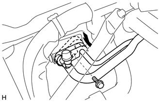
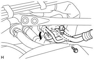
CONNECT VACUUM TUBE CONNECTOR HOSE (for Manual Transmission)
-
Connect the vacuum tube connector hose with the bolt.
- Torque:
- 18 N*m { 184 kgf*cm, 13 ft.*lbf }
-
Connect the vacuum tube connector hose.
-
-
CONNECT VACUUM TUBE CONNECTOR HOSE (for Automatic Transmission)
-
Connect the vacuum tube connector hose with the 2 bolts.
- Torque:
- 18 N*m { 184 kgf*cm, 13 ft.*lbf }
-
Connect the vacuum tube connector hose.
-
-
INSTALL NO. 1 ENGINE COVER SUB-ASSEMBLY (w/ Air Conditioning System)
-
CONNECT ENGINE WIRE (for RHD)
-
Connect the generator connector and connect the clamp.
-
Connect the generator wire with the nut.
- Torque:
- 16 N*m { 163 kgf*cm, 12 ft.*lbf }
-
Install the terminal cap.
-
Connect the 5 wire harness clamps.
-
Install the 2 wire harness clamp brackets with the 2 bolts.
- Torque:
- 11 N*m { 112 kgf*cm, 8 ft.*lbf }
-
Connect the 2 wire harness clamps to the 2 wire harness clamp brackets.
-
Connect the wire harness clamp to the No. 2 engine hanger.
-
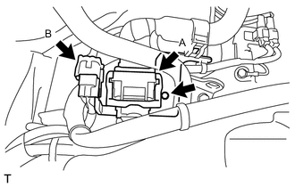
Connect the connector (B).
-
Connect the wire harness connector (A) and securely lock the connector.
-
Install the wire harness clamp bracket to the No. 2 engine hanger with the bolt.
- Torque:
- 10 N*m { 102 kgf*cm, 7 ft.*lbf }
-
for Automatic Transmission:
-
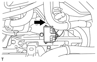
Slide the connector in the direction shown in the diagram, and connect the wire harness.
-
Connect the 2 wire harness clamps.
-
Connect the wire harness connector (A) and securely lock the connector.
-
Connect the connector (B).
-
-
-
CONNECT ENGINE WIRE (for LHD)
-
Connect the generator connector and connect the clamp.
-
Connect the generator wire with the nut.
- Torque:
- 16 N*m { 163 kgf*cm, 12 ft.*lbf }
-
Install the terminal cap.
-
Connect the 5 wire harness clamps.
-
Install the 2 wire harness clamp brackets with the 2 bolts.
- Torque:
- 11 N*m { 112 kgf*cm, 8 ft.*lbf }
-
Connect the 2 wire harness clamps to the 2 wire harness clamp brackets.
-
Connect the wire harness clamp to the No. 2 engine hanger.
-
Connect the connector (B).
-
Connect the wire harness connector (A) and securely lock the connector.
-
Install the wire harness clamp bracket to the No. 2 engine hanger with the bolt.
- Torque:
- 10 N*m { 102 kgf*cm, 7 ft.*lbf }
-
for Automatic Transmission:
-
Slide the connector in the direction shown in the diagram, and connect the wire harness.
-
Connect the 2 wire harness clamps.
-
Connect the wire harness connector (A) and securely lock the connector.
-
Connect the connector (B).
-
-
-
INSTALL INJECTOR DRIVER
-
INSTALL WATER FILLER SUB-ASSEMBLY
-
Install the 2 clamps and connect the water filler sub-assembly.
-
Install the water filler sub-assembly with 2 bolts.
- Torque:
- 7.5 N*m { 76 kgf*cm, 66 in.*lbf }
-
-
INSTALL RADIATOR RESERVE TANK ASSEMBLY
-
INSTALL AIR CLEANER ASSEMBLY WITH HOSE
-
Install the stay with bolt to the body.
- Torque:
- 35 N*m { 357 kgf*cm, 26 ft.*lbf }
-
Install the air cleaner assembly with hose with the 3 bolts.
- Torque:
- 6.0 N*m { 61 kgf*cm, 53 in.*lbf }
-
Install the hose clamp.
- Torque:
- 2.0 N*m { 20 kgf*cm, 18 in.*lbf }
-
Connect the clamp and wire harness to the air cleaner cap.
-
Connect the mass air flow meter connector.
-
Connect the No. 2 ventilation hose.
-
Install the 2 bolts and the chamber duct with chamber.
- Torque:
- 6.0 N*m { 61 kgf*cm, 53 in.*lbf }
-
Connect the hose.
-
-
INSTALL FRONT SUSPENSION UPPER TO COWL BRACE SUB-ASSEMBLY LH
-
INSTALL FRONT SUSPENSION UPPER TO COWL BRACE SUB-ASSEMBLY RH
-
ADD ENGINE OIL
-
CONNECT CABLE TO NEGATIVE BATTERY TERMINAL
-
ADD ENGINE COOLANT
-
CHARGE WITH REFRIGERANT (w/ Air Conditioning System)
-
for HFC-134a (R134a):
-
for HFO-1234fy (R1234fy):
-
-
CHECK FOR ENGINE COOLANT LEAK
-
CHECK FOR ENGINE OIL LEAK
-
CHECK FOR FUEL LEAK
-
CHECK FOR EXHAUST GAS LEAK
-
INSPECT FOR REFRIGERANT LEAK
-
for HFC-134a (R134a):
-
for HFO-1234fy (R1234fy):
-
-
INSPECT THROTTLE WITH MOTOR BODY ASSEMBLY
-
INSPECT IGNITION TIMING
-
INSPECT ENGINE IDLE SPEED
-
INSPECT CO/HC
-
INSPECT ENGINE COOLANT LEVEL
-
INSPECT ENGINE OIL LEVEL
-
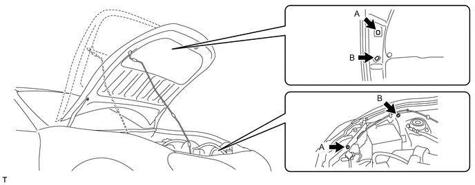
SET HOOD SUB-ASSEMBLY
-
Change the front hood stay position from B to A, and store the front hood stay.
-