ENTRY LOCK AND UNLOCK SWITCH INSTALLATION
CAUTION / NOTICE / HINT
Tech Tips
-
Use the same procedure for the RH and LH sides.
-
The procedure listed below is for the LH side.
PROCEDURE
-
INSTALL FRONT DOOR OUTSIDE HANDLE ASSEMBLY LH
-
Apply MP grease to the sliding area of the front door outside handle assembly LH.
-
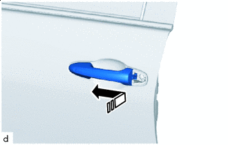

Install in this Direction Install the front door outside handle assembly LH by moving it in the direction indicated by the arrow shown in the illustration.
-
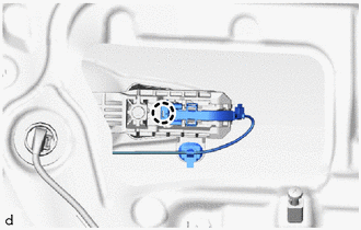
Attach the claw of the connector to connect the connector.
-
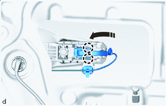
Install in this Direction Attach the claws of the connector cover to connect the connector cover.
-
-
INSTALL FRONT DOOR OUTSIDE HANDLE COVER
-
Apply MP grease to the sliding parts of the lock cylinder.
-
Install the front door outside handle cover with lock cylinder.
-
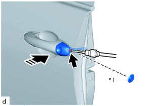
*1 Hole Plug Install in this Direction Using a T30 "TORX" socket wrench, tighten the screw.
- Torque:
- 5.0 N*m { 51 kgf*cm, 44 in.*lbf }
-
Install the hole plug.
-
-
INSTALL FRONT DOOR SERVICE HOLE COVER LH
-
INSTALL FRONT DOOR TRIM BOARD SUB-ASSEMBLY LH
-
INSTALL FRONT ARMREST ASSEMBLY LH
-
INSTALL POWER WINDOW REGULATOR MASTER SWITCH ASSEMBLY WITH FRONT DOOR ARMREST BASE PANEL
-
INSTALL FRONT DOOR INSIDE HANDLE BEZEL PLUG LH
-
INSTALL FRONT DOOR LOWER FRAME BRACKET GARNISH LH