PARKING BRAKE SYSTEM ADJUSTMENT
PROCEDURE
CHECK PARKING BRAKE LEVER TRAVEL
Pull the lever upward with a force of approximately 200 N (20 kgf, 45 lbf) and count the number of clicks.
OK
6 to 8 clicks (without rear brake dragging)
REMOVE REAR WHEEL
REMOVE REAR CONSOLE BOX SUB-ASSEMBLY
ADJUST PARKING BRAKE LEVER TRAVEL
Completely release the parking brake lever.
-
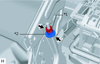
*1
Lock Nut
*2
No. 1 Cable Adjusting Nut
Loosen the lock nut and No. 1 cable adjusting nut to completely release the parking brake cable.
Temporarily install the hub nuts.
-
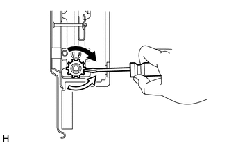

Shoe Adjuster Contracts

Shoe Adjuster Expands
Remove the shoe adjusting hole plug, and then turn the adjuster to expand the shoe adjuster until the disc locks.
Turn the shoe adjuster so that it contracts to a point where the disc can rotate smoothly.
Standard
8 notches
Check that the shoe has no brake drag.
Install the shoe adjusting hole plug.
Remove the hub nuts.
-
*1
Lock Nut
*2
No. 1 Cable Adjusting Nut
Turn the No. 1 cable adjusting nut until the lever travel is correct.
OK
6 to 8 clicks (without rear brake dragging)
<Lever pulling force: approximately 200 N (20 kgf, 45 lbf)>
Tighten the lock nut.
6.0 N*m
61 kgf*cm
53 in.*lbf
Operate the parking brake lever 3 to 4 times, and check the parking brake lever travel.
OK
6 to 8 clicks (without rear brake dragging)
<Lever pulling force: approximately 200 N (20 kgf, 45 lbf)>
When operating the parking brake lever, check that the brake warning light illuminates at the first click.
OK
The brake warning light always illuminates at the first click.
INSTALL REAR CONSOLE BOX SUB-ASSEMBLY
INSTALL REAR WHEEL
103 N*m
1050 kgf*cm
76 ft.*lbf