ENGINE UNIT REMOVAL

PROCEDURE
-
REMOVE ENGINE HANGERS
-
Remove the bolt and engine hanger.
-
-
REMOVE GENERATOR COVER
-
REMOVE BELT GENERATOR COVER
-
REMOVE FAN AND GENERATOR V BELT
-
REMOVE GENERATOR ASSEMBLY
-
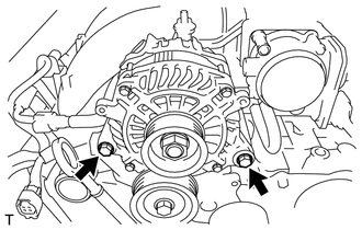
Remove the 2 bolts and generator assembly.
-
-
REMOVE OIL LEVEL DIPSTICK GUIDE
-
REMOVE NO. 2 IDLER PULLEY SUB-ASSEMBLY
-
REMOVE V-RIBBED BELT TENSIONER ASSEMBLY
-

Remove the cap.
-
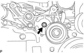
Using an 8 mm hexagon wrench, remove the bolt and V-ribbed belt tensioner assembly.
-
-
REMOVE GENERATOR BRACKET
-
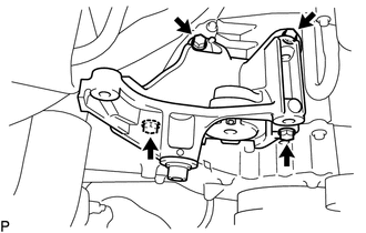
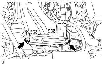
Remove the 4 bolts and generator bracket.
-
-
REMOVE COMPRESSOR WITH MAGNET CLUTCH
-
REMOVE INJECTOR COVER (for Bank 2)
-
for Resin Intake Manifold:
-
Remove the 2 bolts and injector cover.
-
-
for Aluminum Intake Manifold:
-
Remove the 2 bolts and disengage the 2 guides, and then remove the injector cover.
-
-
-
REMOVE INJECTOR COVER (for Bank 1)
-
for Resin Intake Manifold:
-
Remove the 2 bolts and injector cover.
-
-
for Aluminum Intake Manifold:
-
Remove the 2 bolts and disengage the 2 guides, and then remove the injector cover.
-
-
-
REMOVE FUEL DELIVERY PIPE SUB-ASSEMBLY
-
Remove the bolt and disconnect the fuel delivery pipe sub-assembly.
-
Disconnect the No. 2 fuel vapor feed hose.
-
Remove the union bolt and gasket, and disconnect the fuel delivery pipe sub-assembly.
-
-
SEPARATE VENTILATION HOSE
-
REMOVE INTAKE MANIFOLD
-
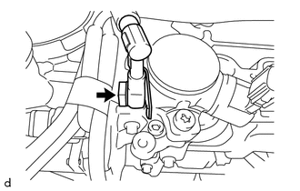
Disconnect the throttle body assembly connector.
-
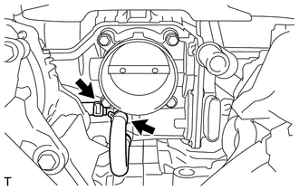
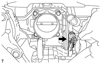
Disconnect the 2 water by-pass hoses from the throttle body assembly.
-
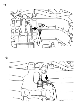
Text in Illustration *A for Resin Intake Manifold *B for Aluminum Intake Manifold Disconnect the vacuum sensor connector.
-
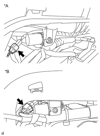
Text in Illustration *A for Resin Intake Manifold *B for Aluminum Intake Manifold Disconnect the No. 1 vacuum switching valve assembly connector.
-
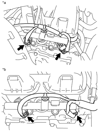
Text in Illustration *a for Bank 2 *b for Bank 1 Disengage the 2 clamps and disconnect the 4 connectors.
-
Disconnect the wire harness.
-
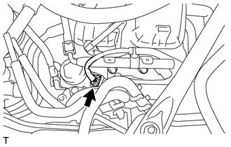
Disconnect the fuel pump connector.
-
for Resin Intake Manifold:
-
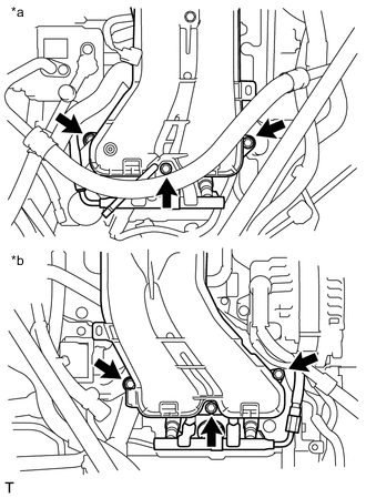
Text in Illustration *a for Bank 2 *b for Bank 1 Remove the 6 bolts, intake manifold and 2 gaskets.
-
-
for Aluminum Intake Manifold:
-
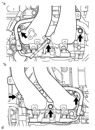
Text in Illustration *a for Bank 2 *b for Bank 1 Remove the 6 bolts, intake manifold and 2 gaskets.
-
-
-
REMOVE NO. 2 FUEL DELIVERY PIPE
-
REMOVE FUEL DELIVERY PIPE
-
REMOVE FUEL DELIVERY PIPE LH
-
REMOVE FUEL DELIVERY PIPE RH
-
REMOVE FUEL INJECTOR ASSEMBLY
-
REMOVE FUEL INJECTOR O-RING
-
REMOVE FUEL PUMP ASSEMBLY
-
REMOVE VALVE LIFTER
-
REMOVE PUMP DRIVE CASE ASSEMBLY
-
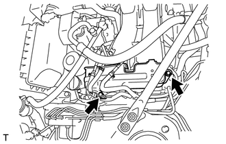
REMOVE ENGINE WIRE
-
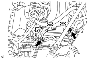
Remove the 2 bolts and separate the ground wire harness.
-
Disconnect each connector and clamp, and remove the engine wire.
-
-
REMOVE NO. 2 VENTILATION HOSE
-
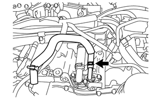
Disconnect the No. 2 ventilation hose.
-
-
REMOVE NO. 2 WATER BY-PASS HOSE
-
Disconnect the No. 2 water by-pass hose.
-
-
REMOVE NO. 3 TRANSMISSION OIL COOLER HOSE (for Automatic Transmission)
-
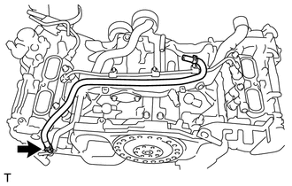
Disconnect the No. 3 transmission oil cooler hose.
-
-
REMOVE NO. 1 WATER BY-PASS PIPE (for Manual Transmission)
-
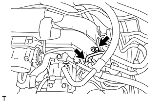
Loosen the hose clip and disconnect the water by-pass hose.
-
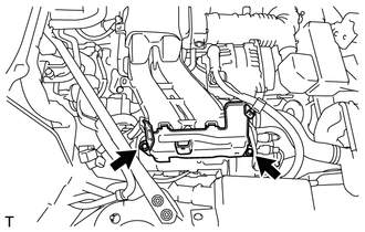
Remove the 2 bolts and the No. 1 water by-pass pipe.
-
-
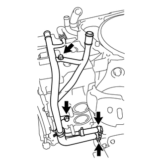
REMOVE NO. 1 WATER BY-PASS PIPE (for Automatic Transmission)
-
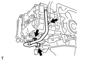
Loosen the 2 hose clips and disconnect the 2 water by-pass hoses.
-
Remove the 2 bolts and No. 1 water by-pass pipe.
-
-
REMOVE IGNITION COIL ASSEMBLY
-
Remove the 4 bolts and 4 ignition coil assemblies.
-