PANORAMIC VIEW MONITOR SWITCH INSPECTION
PROCEDURE
-
INSPECT INTEGRATION CONTROL AND PANEL ASSEMBLY (for LHD)
-
Remove the integration control and panel assembly (panoramic view monitor switch).
-
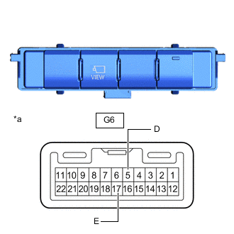
*a Component without harness connected
(Integration Control and Panel Assembly (Panoramic View Monitor Switch))
Measure the resistance according to the value(s) in the table below.
Standard Resistance Tester Connection Switch Condition Specified Condition G6-5 (D) - G6-17 (E) Panoramic view monitor switch on (not protruding) Below 1 Ω Panoramic view monitor switch off (protruding) 10 kΩ or higher If the result is not as specified, replace the integration control and panel assembly (panoramic view monitor switch).
-
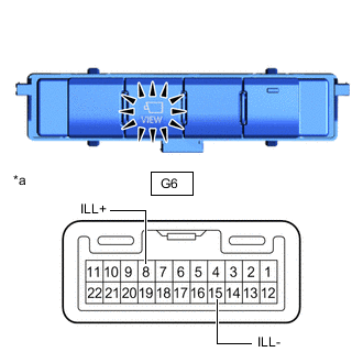
*a Component without harness connected
(Integration Control and Panel Assembly (Panoramic View Monitor Switch))
Check the illumination.
-
Apply battery voltage to the connector and check the illumination conditions.
OK Tester Connection Specified Condition G6-8 (ILL+) - Battery positive (+)
G6-15 (ILL-) - Battery negative (-)
Illuminates If the result is not as specified, replace the integration control and panel assembly (panoramic view monitor switch).
-
-
Install the integration control and panel assembly (panoramic view monitor switch).
-
-
INSPECT INTEGRATION CONTROL AND PANEL ASSEMBLY (for RHD)
-
Remove the integration control and panel assembly (panoramic view monitor switch).
-
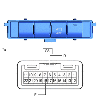
*a Component without harness connected
(Integration Control and Panel Assembly (Panoramic View Monitor Switch))
Measure the resistance according to the value(s) in the table below.
Standard Resistance Tester Connection Switch Condition Specified Condition G6-6 (D) - G6-18 (E) Panoramic view monitor switch on (not protruding) Below 1 Ω Panoramic view monitor switch off (protruding) 10 kΩ or higher If the result is not as specified, replace the integration control and panel assembly (panoramic view monitor switch).
-
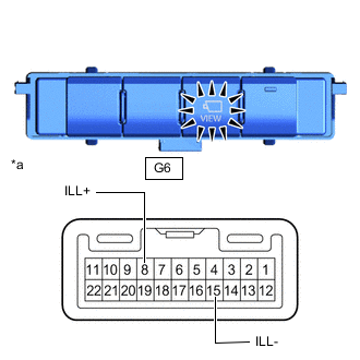
*a Component without harness connected
(Integration Control and Panel Assembly (Panoramic View Monitor Switch))
Check the illumination.
-
Apply battery voltage to the connector and check the illumination conditions.
OK Tester Connection Specified Condition G6-8 (ILL+) - Battery positive (+)
G6-15 (ILL-) - Battery negative (-)
Illuminates If the result is not as specified, replace the integration control and panel assembly (panoramic view monitor switch).
-
-
Install the integration control and panel assembly (panoramic view monitor switch).
-