ELECTRONIC SHIFT LEVER SYSTEM(for 8GR-FKS) "Shift system malfunction Stop in a safe place See owner's manual" is Displayed on Multi-information Display
CAUTION / NOTICE / HINT
Note
The vehicle is equipped with a sub-battery. Therefore, ensure there is no power being supplied to the vehicle when disconnecting or reconnecting the connector of the shift control ECU and when removing or installing the shift control ECU.
PROCEDURE
-
CHECK DTC OUTPUT (TRANSMISSION)
-
Connect the GTS to the DLC3.
-
Turn the engine switch on (IG).
-
With the brake pedal depressed, while slowly move the shift lever as follows: N → R → N → D → M.
Tech Tips
Wait with the shift lever in each position for 5 seconds or more.
-
Push the P position switch (shift position indicator) to select park (P).
-
Enter the following menus: Powertrain / Transmission / Trouble Codes.
Powertrain > Transmission > Trouble Codes -
Check if DTCs are output.
Result Result Proceed to None of the DTCs are output. A Any of the DTCs are output. B -
Turn the engine switch off.
B 
GO TO DTC CHART Click here
A 
-
-
CHECK CONNECTOR CONNECTION CONDITION (SHIFT CONTROL ECU CONNECTOR)
-
Check the connector connections and contact pressure of the relevant terminals for the shift control ECU connectors.
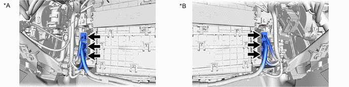
*A for LHD *B for RHD OK The connectors are connected securely and there are no contact pressure problems. Result Proceed to OK NG
NG
CONNECT SECURELY
OK
-
-
CHECK CONNECTOR CONNECTION CONDITION (SHIFT LEVER POSITION SENSOR (TRANSMISSION FLOOR SHIFT ASSEMBLY))
-
Check the connector connections and contact pressure of the relevant terminals for the shift lever position sensor (transmission floor shift assembly) connector.
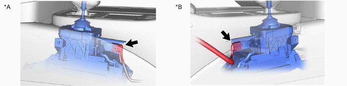
*A for LHD *B for RHD OK The connector is connected securely and there are no contact pressure problems. Result Proceed to OK NG
NG
CONNECT SECURELY
OK
-
-
CHECK HARNESS AND CONNECTOR (SHIFT CONTROL ECU - SHIFT LEVER POSITION SENSOR (TRANSMISSION FLOOR SHIFT ASSEMBLY))
-
Disconnect the G82 shift control ECU connector.
-
Disconnect the G83 shift lever position sensor (transmission floor shift assembly) connector.
-
Measure the resistance according to the value(s) in the table below.
Standard Resistance (Check for Open) Tester Connection Condition Specified Condition G82-20 (VCX1) - G83-4 (VCX1) Always Below 1 Ω G82-22 (VCX2) - G83-12 (VCX2) Always Below 1 Ω G82-19 (VSI1) - G83-7 (VSX1) Always Below 1 Ω G82-21 (VSI2) - G83-5 (VSX2) Always Below 1 Ω G82-23 (VSI3) - G83-11 (VSX3) Always Below 1 Ω G82-25 (VSI4) - G83-9 (VSX4) Always Below 1 Ω G82-24 (E2X1) - G83-14 (E2X1) Always Below 1 Ω G82-26 (E2X2) - G83-2 (E2X2) Always Below 1 Ω Standard Resistance (Check for Short) Tester Connection Condition Specified Condition G82-20 (VCX1) or G83-4 (VCX1) - Body ground and other terminals Always 10 kΩ or higher G82-22 (VCX2) or G83-12 (VCX2) - Body ground and other terminals Always 10 kΩ or higher G82-19 (VSI1) or G83-7 (VSX1) - Body ground and other terminals Always 10 kΩ or higher G82-21 (VSI2) or G83-5 (VSX2) - Body ground and other terminals Always 10 kΩ or higher G82-23 (VSI3) or G83-11 (VSX3) - Body ground and other terminals Always 10 kΩ or higher G82-25 (VSI4) or G83-9 (VSX4) - Body ground and other terminals Always 10 kΩ or higher G82-24 (E2X1) or G83-14 (E2X1) - Body ground and other terminals Always 10 kΩ or higher G82-26 (E2X2) or G83-2 (E2X2) - Body ground and other terminals Always 10 kΩ or higher -
Reconnect the G83 shift lever position sensor (transmission floor shift assembly) connector.
-
Reconnect the G82 shift control ECU connector.
Result Proceed to OK NG
OK
CHECK FOR INTERMITTENT PROBLEMS Click here
NG
REPAIR OR REPLACE HARNESS OR CONNECTOR
-