BLOCKING SYSTEM, Diagnostic DTC:B15C0, B15C1
| DTC Code | DTC Name |
|---|---|
| B15C0 | Short in GPS Antenna |
| B15C1 | Open in GPS Antenna |
DESCRIPTION
These DTCs are stored when a malfunction occurs in the navigation antenna assembly (GPS antenna) circuit.
| DTC No. | Detection Item | DTC Detection Condition | Trouble Area |
|---|---|---|---|
| B15C0 | Short in GPS Antenna | A short circuit in the navigation antenna assembly between the telephone transceiver assembly and navigation antenna assembly (GPS antenna), or at the points where it connects to the telephone transceiver assembly and navigation antenna assembly is detected. |
|
| B15C1 | Open in GPS Antenna | An open circuit in the navigation antenna assembly between the telephone transceiver assembly and navigation antenna assembly (GPS antenna), or at the points where it connects to the telephone transceiver assembly and navigation antenna assembly is detected. |
|
CAUTION / NOTICE / HINT
Note
-
When replacing the telephone transceiver assembly or navigation antenna assembly, refer to Service Bulletin.
-
When the telephone transceiver assembly is replaced, it is necessary to set the contract mode.
PROCEDURE
-
CHECK CONNECTION OF CONNECTORS
-
Turn the engine switch off.
-
Check that the connectors are properly connected to the telephone transceiver assembly and navigation antenna assembly (GPS antenna) connector.
OK Connectors are properly connected. Result Proceed to OK NG
NG 
CONNECT CONNECTORS CORRECTLY
OK 
-
-
CLEAR DTC
-
Clear the DTCs.
Body Electrical > Telematics > Clear DTCsResult Proceed to NEXT
NEXT
-
-
CHECK FOR DTC
-
Check for DTCs.
Body Electrical > Telematics > Trouble CodesOK DTCs B15C0 and B15C1 are not output. Result Proceed to OK NG
OK
USE SIMULATION METHOD TO CHECK Click here
NG
-
-
CHECK CONNECTOR CONDITION
-
Turn the engine switch off.
-
Disconnect the I144 telephone transceiver assembly (GPS antenna) connector.

*a Component without harness connected
(Telephone Transceiver Assembly)
*b GPS Antenna -
Check that the connector pins are not bent.
OK Connector pins are not bent. Result Proceed to OK NG
NG
REPLACE TELEPHONE TRANSCEIVER ASSEMBLY
OK
-
-
CHECK NAVIGATION ANTENNA ASSEMBLY (TELEPHONE ANTENNA)
-
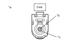
*a Component without harness connected
(Navigation Antenna Assembly (GPS Antenna))
*b Core Wire *c Shield Disconnect the I144 telephone transceiver assembly (GPS antenna) connector.
-
Measure the resistance according to the value(s) in the table below.
Standard Resistance Tester Connection Condition Specified Condition Core wire - Shield Always 50 to 500 Ω Result Proceed to OK NG
NG 
CHECK HARNESS AND CONNECTOR (TELEPHONE TRANSCEIVER ASSEMBLY - NAVIGATION ANTENNA ASSEMBLY) Click here
OK
-
-
CLEAR DTC
-
Clear the DTCs.
Body Electrical > Telematics > Clear DTCsResult Proceed to NEXT
NEXT
-
-
CHECK FOR DTC
-
Check for DTCs.
Body Electrical > Telematics > Trouble CodesOK DTCs B15C0 and B15C1 are not output. Result Proceed to OK NG
OK
USE SIMULATION METHOD TO CHECK Click here
NG
REPLACE NAVIGATION ANTENNA ASSEMBLY Click here
-
-
CHECK HARNESS AND CONNECTOR (TELEPHONE TRANSCEIVER ASSEMBLY - NAVIGATION ANTENNA ASSEMBLY)
-
Disconnect the I144 telephone transceiver assembly (GPS antenna) connector.
-
Disconnect the I146 navigation antenna assembly connector.
-
Measure the resistance according to the value(s) in the table below.
Standard Resistance Tester Connection Condition Specified Condition I144-1 (GPS) - I146-3 (GPS) Always Below 1 Ω I144-1 (GPS) - Body ground Always 10 kΩ or higher I146-3 (GPS) - Body ground Always 10 kΩ or higher Result Proceed to OK NG
OK
REPLACE NAVIGATION ANTENNA ASSEMBLY
NG
REPAIR OR REPLACE HARNESS OR CONNECTOR
-
-
REPLACE NAVIGATION ANTENNA ASSEMBLY
-
Temporarily replace the navigation antenna assembly with a new or known good one.
Tech Tips
Refer to Service Bulletin.
Result Proceed to NEXT
NEXT
-
-
CLEAR DTC
-
Clear the DTCs.
Body Electrical > Telematics > Clear DTCsResult Proceed to NEXT
NEXT
-
-
CHECK FOR DTC
-
Check for DTCs.
Body Electrical > Telematics > Trouble CodesOK DTCs B15C0 and B15C1 are not output. Result Proceed to OK NG
OK
END (NAVIGATION ANTENNA ASSEMBLY WAS DEFECTIVE)
NG
REPLACE TELEPHONE TRANSCEIVER ASSEMBLY
-