БЛОК ДВИГАТЕЛЯ УСТАНОВКА

Note
-
When replacing the parts in the following chart (A), replace the No. 1 injection pipe sub-assembly, No. 2 injection pipe sub-assembly and/or fuel inlet pipe sub-assembly with new ones.
Replaced Parts (A) Pipes Requiring New Replacement Injector assembly (including shuffling the injector assemblies between the cylinders)
-
No. 1 injection pipe sub-assembly
-
No. 2 injection pipe sub-assembly
Supply pump assembly Fuel inlet pipe sub-assembly
-
Common rail assembly
-
Cylinder block sub-assembly
-
Cylinder head sub-assembly
-
Cylinder head gasket
-
Timing chain case assembly
-
No. 1 injection pipe sub-assembly
-
No. 2 injection pipe sub-assembly
-
Fuel inlet pipe sub-assembly
-
-
After removing the No. 1 injection pipe sub-assembly, No. 2 injection pipe sub-assembly and/or fuel inlet pipe sub-assembly, clean them with a brush and compressed air.
-
The injector assembly is a precision instrument. Do not use the injector assembly if it is struck or dropped.
-
The supply pump assembly is a precision instrument. Do not use the supply pump assembly if it is struck or dropped.
-
The common rail assembly is a precision instrument. Do not use the common rail assembly if it is struck or dropped.
-
Hold the supply pump assembly itself during removal and installation. Do not hold the pre-stroke control valve or fuel pipe, etc.
-
Hold the common rail assembly itself during removal and installation. Do not hold the pressure discharge valve or fuel pressure sensor, etc.
-
Make sure foreign matter does not enter the fuel path.
-
TEMPORARILY INSTALL FAN PULLEY
-
Temporarily install the fan pulley and water pump spacer to the engine water pump assembly with the 4 nuts.
-
-
TIGHTEN FAN PULLEY
-
Tighten the 4 nuts and install the fan pulley.
- Torque:
- 23 N*m { 235 kgf*cm, 17 ft.*lbf }
-
-
INSTALL PCV HOSE CLAMP
-
Install the PCV hose clamp to the timing chain case assembly and timing chain cover sub-assembly with the 2 bolts.
- Torque:
- 10 N*m { 102 kgf*cm, 7 ft.*lbf }
-
-
INSTALL CRANKSHAFT PULLEY
-
Align the keyway of the crankshaft pulley with the key located on the crankshaft, and then slide the crankshaft pulley into place to install it.
-
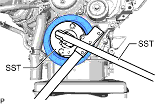
Using SST, install a new pulley bolt.
- SST
- 09213-58014 ( 91551-80840 )
- 09330-00021
- Torque:
- 365 N*m { 3722 kgf*cm, 269 ft.*lbf }
-
-
INSTALL CRANKSHAFT PULLEY COVER
-
Install the crankshaft pulley cover to the crankshaft pulley with the 4 bolts.
- Torque:
- 21 N*m { 214 kgf*cm, 15 ft.*lbf }
-
-
INSTALL CAMSHAFT OIL SEAL RETAINER
Note
If the camshaft oil seal retainer is dropped, replace it with a new one.
-
Before installing a new camshaft oil seal retainer, clean the installation surface of the No. 3 camshaft bearing cap and cylinder head sub-assembly and remove any foreign matter.
-
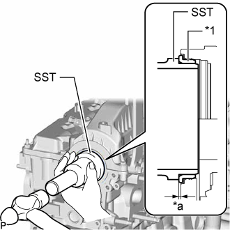
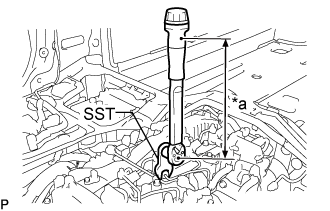
Text in Illustration *1 Camshaft Oil Seal Retainer *a Depth Using SST and a hammer, tap in a new camshaft oil seal retainer to the No. 3 camshaft bearing cap and cylinder head sub-assembly as shown in the illustration.
- SST
- 09223-22010
Standard depth -0.5 to 0.8 mm (-0.0197 to 0.0315 in.)
-
-
INSTALL NO. 1 VACUUM TRANSMITTING PIPE SUB-ASSEMBLY
-
Install the No. 1 vacuum transmitting pipe sub-assembly to the cylinder head sub-assembly and cylinder block sub-assembly with the 3 bolts.
- Torque:
- 10 N*m { 102 kgf*cm, 7 ft.*lbf }
-
-
INSTALL VACUUM PUMP ASSEMBLY
-
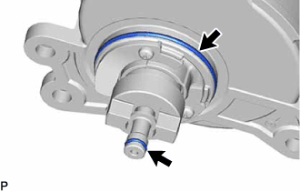
Coat 2 new O-rings with engine oil, and install them to the vacuum pump assembly.
-
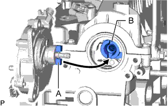
Install the vacuum pump assembly so that the coupling teeth of the vacuum pump assembly labeled A and the groove of the No. 2 camshaft labeled B can engage.
-
Install the vacuum pump assembly to the cylinder head sub-assembly with the 3 bolts.
- Torque:
- 21 N*m { 214 kgf*cm, 15 ft.*lbf }
-
Connect the No. 1 vacuum transmitting hose sub-assembly to the vacuum pump assembly.
-
-
INSTALL V-RIBBED BELT TENSIONER ASSEMBLY
-
Install the V-ribbed belt tensioner assembly to the timing chain cover sub-assembly with the 3 bolts.
- Torque:
- 21 N*m { 214 kgf*cm, 15 ft.*lbf }
-
-
INSTALL NO. 1 IDLER PULLEY SUB-ASSEMBLY
-
Install the No. 1 idler pulley sub-assembly to the generator bracket sub-assembly with the bolt.
- Torque:
- 43 N*m { 438 kgf*cm, 32 ft.*lbf }
-
-
INSTALL THERMOSTAT
-
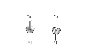
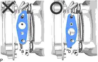
Text in Illustration *1 Gasket *a CORRECT *b INCORRECT Install a new gasket to the thermostat as shown in the illustration.
Note
When installing the gasket to the thermostat, be careful not to deform the gasket. Make sure that the groove of the gasket is properly installed to the thermostat as shown in the illustration.
-
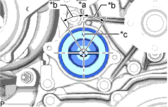
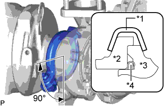
Text in Illustration *a Upward *b 30° *c Jiggle Valve Insert the thermostat into the engine water pump assembly with the jiggle valve facing straight upward.
Tech Tips
The jiggle valve may be set to within 30° on either side of the prescribed position.
-
-
INSTALL WATER INLET
-
Install the water inlet to the engine water pump assembly with the 2 bolts.
- Torque:
- 13 N*m { 133 kgf*cm, 10 ft.*lbf }
-
-
INSTALL WATER OUTLET SUB-ASSEMBLY
-
Install a new gasket and the water outlet sub-assembly to the timing chain cover sub-assembly with the 4 bolts and 2 nuts.
- Torque:
- 10 N*m { 102 kgf*cm, 7 ft.*lbf }
-
-
INSTALL NO. 2 WATER BY-PASS PIPE SUB-ASSEMBLY
-
Install the No. 2 water by-pass pipe sub-assembly to the engine water pump assembly and water inlet with the 2 bolts.
- Torque:
- 10 N*m { 102 kgf*cm, 7 ft.*lbf }
-
Connect the No. 3 water by-pass hose to the water outlet sub-assembly, and slide the clamp to secure the hose.
-
-
INSTALL ENGINE OIL PRESSURE SWITCH ASSEMBLY
-
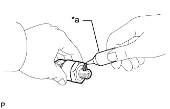
Text in Illustration *a Adhesive Apply adhesive to 2 or 3 threads of the engine oil pressure switch assembly.
Adhesive Toyota Genuine Adhesive 1344, Three Bond 1344 or equivalent Note
Do not apply adhesive to the oil inlet port of the engine oil pressure switch assembly.
-
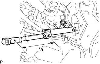
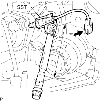
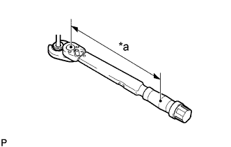
Text in Illustration *a Torque Wrench Fulcrum Length Using SST and a 24 mm deep socket wrench, install the engine oil pressure switch assembly to the oil filter bracket.
- SST
- 09961-01270
- Torque:
- Specified tightening torque
- 15 N*m { 153 kgf*cm, 11 ft.*lbf }
Tech Tips
-
Calculate the torque wrench reading when changing the fulcrum length of the torque wrench.
-
When using SST (fulcrum length of 200 mm (7.87 in.)) + torque wrench (fulcrum length of 162 mm (6.38 in.)): 7.0 N*m (68 kgf*cm, 59 in.*lbf)
Note
Do not start the engine for at least 1 hour after the installation.
-
-
TEMPORARILY INSTALL TURBO OIL INLET PIPE SUB-ASSEMBLY
-
Text in Illustration *a NG *b OK Install a new gasket as shown in the illustration.
Note
Do not install the gasket upside down.
-
Temporarily install the turbo oil inlet pipe sub-assembly with the 2 nuts.
-
-
TEMPORARILY INSTALL EXHAUST MANIFOLD WITH TURBOCHARGER SUB-ASSEMBLY
-
Install 2 new gaskets to the exhaust manifold and turbocharger sub-assembly.
-
Temporarily install the exhaust manifold to turbocharger sub-assembly with 3 new nuts.
-
Text in Illustration *1 Collar 
Engine Side Temporarily install the exhaust manifold with turbocharger sub-assembly, 8 collars and 8 plate washers to the cylinder head sub-assembly with 8 new nuts.
Note
Make sure that the side of the collar with the smaller diameter faces the exhaust manifold.
-
Install a new gasket on the union bolt side to turbo oil inlet pipe sub-assembly.
-
Temporarily install the union bolt.
-
-
INSTALL TURBO OIL OUTLET PIPE
-
Install a new gasket to the turbo oil outlet pipe.
Note
The claws of the gasket must face the turbo oil outlet pipe.
-
Install the turbo oil outlet pipe with the 2 bolts.
- Torque:
- 12 N*m { 122 kgf*cm, 9 ft.*lbf }
-
Connect the turbo oil outlet hose to the turbo oil outlet pipe, turbo oil inlet pipe and slide the 2 hose clips to secure the hoses.
-
-
TEMPORARILY INSTALL TURBOCHARGER STAY
-
Temporarily install the turbocharger stay to the turbocharger sub-assembly with the 3 bolts and nut.
-
-
TIGHTEN EXHAUST MANIFOLD WITH TURBOCHARGER SUB-ASSEMBLY
-
Tighten the exhaust manifold with turbocharger sub-assembly to the cylinder head sub-assembly with the 8 nuts.
- Torque:
- 40 N*m { 408 kgf*cm, 30 ft.*lbf }
Tech Tips
Tighten the nuts in the order shown in the illustration.
-
Tighten the turbocharger sub-assembly to the exhaust manifold with the 3 nuts.
- Torque:
- 73 N*m { 744 kgf*cm, 54 ft.*lbf }
-
Tighten the 2 nuts and union bolt of the turbo oil inlet pipe sub-assembly.
- Torque:
- for nut
- 13 N*m { 133 kgf*cm, 10 ft.*lbf }
- for union bolt
- 36 N*m { 367 kgf*cm, 27 ft.*lbf }
Note
If the connecting part of the union bolt gasket is cracked, remove the connecting part.
-
-
TIGHTEN TURBOCHARGER STAY
-
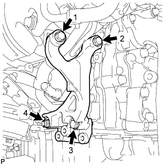
Tighten the 3 bolts and nut of the turbocharger stay in the order shown in the illustration.
- Torque:
- 24 N*m { 245 kgf*cm, 18 ft.*lbf }
-
-
CONNECT NO. 1 AND NO. 2 TURBO WATER HOSE
Note
The turbocharger sub-assembly may be damaged if the No. 1 turbo water hose and No. 2 turbo water hose are connected to the wrong locations.
-
Connect the No. 2 turbo water hose to the water outlet sub-assembly, and slide the 2 hose clips to secure the hoses.
-
Connect the No. 1 turbo water hose to the engine water pump assembly, and slide the 2 hose clips to secure the hoses.
-
-
INSTALL NO. 1 WATER BY-PASS PIPE
-
Install a new gasket and the No. 1 water by-pass pipe to the timing chain cover sub-assembly with the 2 bolts.
- Torque:
- 10 N*m { 102 kgf*cm, 7 ft.*lbf }
Tech Tips
Make sure that the claw of the gasket faces the No. 1 water by-pass pipe.
-
-
INSTALL FRONT ENGINE MOUNTING INSULATOR
-
Install the front engine mounting insulator and engine mounting stabilizer to the front No. 1 engine mounting bracket RH with the nut.
- Torque:
- 86 N*m { 877 kgf*cm, 63 ft.*lbf }
-
-
INSTALL FRONT ENGINE MOUNTING INSULATOR RH
-
Install the front engine mounting insulator RH to the engine mounting stabilizer with the nut.
- Torque:
- 8.0 N*m { 82 kgf*cm, 71 in.*lbf }
-
-
INSTALL EXHAUST MANIFOLD CONVERTER SUB-ASSEMBLY
-
Set a new gasket and the exhaust manifold converter sub-assembly to the turbocharger sub-assembly.
-
Temporarily install the exhaust pipe support stay to the cylinder block sub-assembly and exhaust manifold converter sub-assembly with the 3 bolts.
-
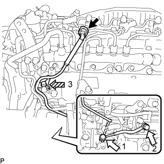
Text in Illustration *1 Exhaust Pipe Clamp *2 Exhaust Manifold Converter *3 Turbocharger Sub-assembly *4 Gasket Install a new exhaust pipe clamp to the exhaust manifold converter sub-assembly with a new nut.
- Torque:
- 18 N*m { 184 kgf*cm, 13 ft.*lbf }
-
Tighten the 3 bolts and install the exhaust pipe support stay to the cylinder block sub-assembly and exhaust manifold converter sub-assembly.
- Torque:
- 38 N*m { 387 kgf*cm, 28 ft.*lbf }
-
-
INSTALL NO. 2 EXHAUST PIPE SUPPORT STAY
-
Install the No. 2 exhaust pipe support stay to the cylinder block sub-assembly and exhaust manifold converter sub-assembly with the bolt and 2 new nuts.
- Torque:
- 38 N*m { 387 kgf*cm, 28 ft.*lbf }
-
-
INSTALL NO. 1 TURBO INSULATOR
-
Install the No. 1 turbo insulator to the exhaust manifold and turbocharger sub-assembly with the 3 bolts.
- Torque:
- 12 N*m { 122 kgf*cm, 9 ft.*lbf }
-
-
INSTALL NO. 1 EXHAUST MANIFOLD HEAT INSULATOR
-
Install the No. 1 exhaust manifold heat insulator to the exhaust manifold with the 3 bolts.
- Torque:
- 12 N*m { 122 kgf*cm, 9 ft.*lbf }
-
-
INSTALL AIR FUEL RATIO SENSOR
Tech Tips
Perform "Inspection After Repairs" after replacing the air fuel ratio sensor Click here.
-
Text in Illustration *a Torque Wrench Fulcrum Length Using SST, install the air fuel ratio sensor to the front exhaust pipe.
- SST
- 09224-00012
- Torque:
- Specified tightening torque
- 44 N*m { 449 kgf*cm, 32 ft.*lbf }
Tech Tips
-
Calculate the torque wrench reading when changing the fulcrum length of the torque wrench Click here.
-
When using SST (fulcrum length of 30 mm (1.18 in.)) + torque wrench (fulcrum length of 180 mm (7.09 in.)): 38 N*m (384 kgf*cm, 28 ft.*lbf)
-
Connect the connector.
-
-
INSTALL NO. 2 EXHAUST MANIFOLD HEAT INSULATOR
-
Install a new gasket and the No. 2 exhaust manifold heat insulator to the No. 1 injector holder with the 3 nuts.
- Torque:
- 10 N*m { 102 kgf*cm, 7 ft.*lbf }
-
-
INSTALL NO. 1 INJECTOR HOLDER
-
Install the No. 1 injector holder to the exhaust manifold with 3 new nuts.
- Torque:
- 43 N*m { 438 kgf*cm, 32 ft.*lbf }
-
Connect the connector to the exhaust fuel addition injector assembly.
-
-
CONNECT NO. 4 WATER BY-PASS HOSE
-
Connect the No. 4 water by-pass hose to the No. 1 injector holder, and slide the clamp to secure the hose.
-
-
INSTALL NO. 5 WATER BY-PASS HOSE
-
Attach the clamp and install the No. 5 water by-pass hose to the hose clamp.
-
Connect the No. 5 water by-pass hose to the No. 1 injector holder and water outlet sub-assembly, and slide the 2 clamps to secure the hose.
-
-
INSTALL PCV HOSE
-
Attach the clamp, install the PCV hose and slide the 2 hose clips to secure the hoses.
-
Slide the 2 hose clips to secure the hoses.
-
-
INSTALL ENGINE COOLANT TEMPERATURE SENSOR
-
Install a new gasket to the engine coolant temperature sensor.
-
Using SST, install the engine coolant temperature sensor to the cylinder head sub-assembly.
- SST
- 09817-33191
- Torque:
- 20 N*m { 200 kgf*cm, 14 ft.*lbf }
-
Connect the engine coolant temperature sensor connector.
-
-
INSTALL NO. 1 COMPRESSOR MOUNTING BRACKET
Note
Install the No. 1 compressor mounting bracket exactly as described in the procedures below to properly secure and prevent damage to the fan and generator V belt.
-
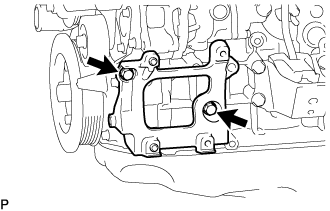
Temporarily install the No. 1 compressor mounting bracket to the cylinder block sub-assembly with the 2 bolts.
Tech Tips
Temporarily install the No. 1 compressor mounting bracket with the 2 bolts so that the No. 1 compressor mounting bracket can be moved by hand.
-
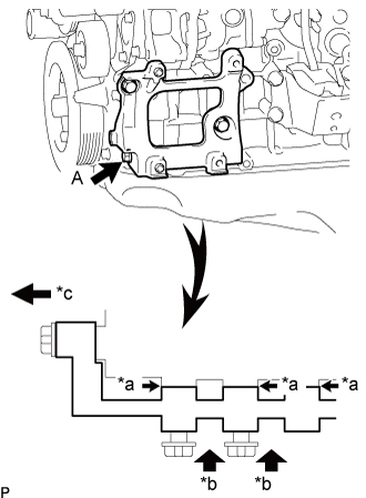
Text in Illustration *a No Clearance *b Push *c Front Push the No. 1 compressor mounting bracket toward the cylinder block sub-assembly as shown in the illustration and tighten bolt A.
- Torque:
- 39 N*m { 398 kgf*cm, 29 ft.*lbf }
Tech Tips
Make sure there is no clearance between the cylinder block sub-assembly and No. 1 compressor mounting bracket as shown in the illustration.
-
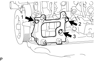
Uniformly tighten the 3 bolts in the order shown in the illustration.
- Torque:
- 39 N*m { 398 kgf*cm, 29 ft.*lbf }
-
-
INSTALL NO. 1 IDLER PULLEY SUB-ASSEMBLY
-
Install the No. 1 idler pulley sub-assembly to the No. 1 compressor mounting bracket with the bolt.
- Torque:
- 43 N*m { 438 kgf*cm, 32 ft.*lbf }
-
-
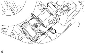
INSTALL COOLER COMPRESSOR ASSEMBLY
-
Установите компрессор системы кондиционирования в сборе и закрепите его 2 шпильками с помощью торцевого ключа "TORX" Е8.
- Torque:
- 10 Н*м { 102 кгс*см, 7 фунт-сила-футов }
-
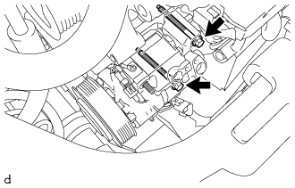
Временно заверните 2 болта.
-
Временно заверните 2 гайки.
-
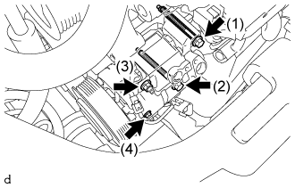
Затяните 2 болта и 2 гайки в последовательности, показанной на рисунке.
- Torque:
- 25 Н*м { 255 кгс*см, 18 фунт-сила-футов }
-
Установите зажим и подсоедините разъем.
-
-
INSTALL NO. 5 WATER BY-PASS PIPE SUB-ASSEMBLY
-
Install a new gasket and the No. 5 water by-pass pipe sub-assembly to the cylinder block sub-assembly with the 3 bolts.
- Torque:
- 25 N*m { 255 kgf*cm, 18 ft.*lbf }
Tech Tips
Make sure that the claw of the gasket faces the No. 5 water by-pass pipe sub-assembly.
-
-
INSTALL FUEL FILTER(for Cylinder Block Side)
-
Install the diesel fuel filter assembly with the 2 nuts to the cylinder block sub-assembly.
- Torque:
- 21 N*m { 214 kgf*cm, 15 ft.*lbf }
-
-
INSTALL BRACKET
-
Install the bracket to the cylinder head sub-assembly with the 2 bolts.
- Torque:
- 10 N*m { 102 kgf*cm, 7 ft.*lbf }
-
-
INSTALL GLOW PLUG ASSEMBLY
Note
-
Measure the resistance of the glow plug assembly when reinstalling it. If the result is not as specified, replace the glow plug assembly with a new one.
-
Replace the glow plug assembly with a new one when it has been dropped or subjected to a physical impact.
-
Remove any carbon deposits from the glow plug hole when reinstalling the glow plug assembly.
-
Clean the glow plug hole.
-
Wrap tape around a drill bit with a diameter of 4.8 mm (0.189 in.), 108.7 mm (4.28 in.) from its tip.
-
Insert the drill bit 108.7 mm (4.28 in.) into the glow plug hole (up to the tape) and remove any carbon deposits by turning the drill bit by hand.
-
Insert a drill bit with a diameter of 3.9 mm (0.154 in.) into the glow plug hole and remove any carbon deposits from the end of the glow plug hole by turning the drill bit by hand.
-
-
Using a 10 mm deep socket wrench, install the 4 glow plug assemblies.
- Torque:
- 18 N*m { 178 kgf*cm, 13 ft.*lbf }
Note
Do not use any tools, such as air tools, which are liable to cause an impact to the glow plug assemblies when installing them.
-
-
INSTALL NO. 1 GLOW PLUG CONNECTOR
-
Temporarily install the No. 1 glow plug connector with the 4 nuts.
-
Tighten the 4 nuts.
- Torque:
- 2.2 N*m { 22 kgf*cm, 19 in.*lbf }
-
Install the 4 glow plug screw grommets.
-
Using an E8 "TORX" socket wrench, install the stud bolt to the intake manifold.
- Torque:
- 10 N*m { 102 kgf*cm, 7 ft.*lbf }
-
-
INSTALL COMMON RAIL ASSEMBLY
-
Install the common rail assembly with the 2 nuts.
- Torque:
- 21 N*m { 214 kgf*cm, 15 ft.*lbf }
-
Connect the fuel pressure sensor connector to the common rail assembly.
-
Attach the wire harness clamp.
-
-
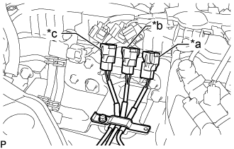
TEMPORARILY INSTALL NO. 1 AND NO. 2 INJECTION PIPE SUB-ASSEMBLY
-
Temporarily install the 2 No. 2 injection pipe sub-assemblies with the 4 union nuts.
-
Temporarily install the 2 No. 1 injection pipe sub-assemblies with the 4 union nuts.
-
-
TIGHTEN INJECTOR ASSEMBLY
-
Tighten the 4 nozzle holder clamp bolts.
- Torque:
- 21 N*m { 214 kgf*cm, 15 ft.*lbf }
-
-
TIGHTEN NO. 1 AND NO. 2 INJECTION PIPE SUB-ASSEMBLY
-
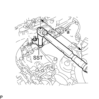
Text in Illustration *a Torque Wrench Fulcrum Length Using SST, tighten the 8 union nuts of the No. 1 and No. 2 injection pipe sub-assemblies.
- Torque:
- Specified tightening torque
- 40 N*m { 408 kgf*cm, 30 ft.*lbf }
Tech Tips
-
Calculate the torque wrench reading when changing the fulcrum length of the torque wrench.
-
When using SST (fulcrum length of 50 mm (1.97 in.)) + torque wrench (fulcrum length of 180 mm (7.09 in.)): 31 N*m (316 kgf*cm, 23 ft.*lbf)
-
-
INSTALL WIRING HARNESS CLAMP BRACKET
-
for Upper Side:
Install the wiring harness clamp bracket to the cylinder head cover sub-assembly with the bolt.
- Torque:
- 10 N*m { 102 kgf*cm, 7 ft.*lbf }
-
for Rear Side:
Install the wiring harness clamp bracket to the cylinder head cover sub-assembly with the bolt.
- Torque:
- 13 N*m { 127 kgf*cm, 9 ft.*lbf }
-
-
INSTALL NOZZLE LEAKAGE PIPE ASSEMBLY
-
Temporarily install the nozzle leakage pipe assembly and 4 new gaskets with the 4 union bolts and bolt.
-
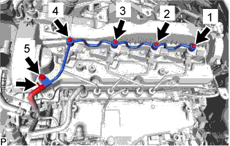
Tighten the 4 union bolts and bolt in the order shown in the illustration.
- Torque:
- for union bolt
- 12 N*m { 122 kgf*cm, 9 ft.*lbf }
- Torque:
- for bolt
- 10 N*m { 102 kgf*cm, 7 ft.*lbf }
-
Connect the No. 5 fuel hose to the nozzle leakage pipe assembly.
-
-
INSTALL NO. 1 FUEL PIPE
-
Connect the No. 1 fuel pipe to the No. 4 fuel pipe.
-
Install a new gasket and the No. 1 fuel pipe to the cylinder head cover sub-assembly and No. 1 injector holder with the union bolt and bolt.
- Torque:
- for bolt
- 10 N*m { 102 kgf*cm, 7 ft.*lbf }
- for union bolt
- 26 N*m { 265 kgf*cm, 19 ft.*lbf }
-
-
INSTALL WIRING HARNESS CLAMP BRACKET
-
Install the wiring harness clamp bracket the cylinder head cover sub-assembly with the bolt.
- Torque:
- 10 N*m { 102 kgf*cm, 7 ft.*lbf }
-
Connect the pressure discharge valve connector to the common rail assembly.
-
-
INSTALL INTAKE MANIFOLD
-
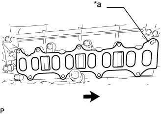
Install a new gasket to the cylinder head sub-assembly.
Tech Tips
Install the gasket with the protrusion facing the rear side of the vehicle as shown in the illustration.
Text in Illustration *a Protrusion 
Rear side -
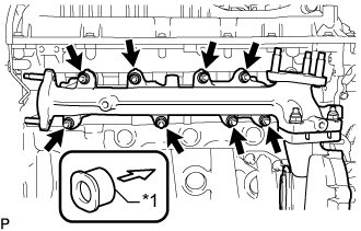
Temporarily install the intake manifold with the 7 bolts and 2 nuts.
-
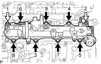
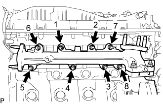
Tighten the 7 bolts and 2 nuts in the order shown in the illustration.
- Torque:
- 23 N*m { 235 kgf*cm, 17 ft.*lbf }
Text in Illustration Bolt Nut -
Connect the wire harness bracket with the bolt.
- Torque:
- 13 N*m { 130 kgf*cm, 9 ft.*lbf }
-
-
INSTALL NO. 2 NOZZLE LEAKAGE PIPE ASSEMBLY
-
Install the No. 2 nozzle leakage pipe assembly with the 2 bolts.
- Torque:
- 10 N*m { 102 kgf*cm, 7 ft.*lbf }
-
Connect the No. 6 fuel hose to the No. 3 nozzle leakage pipe assembly, and slide the clamp to secure the hose.
-
Install the No. 4 fuel hose to the No. 2 nozzle leakage pipe assembly, common rail assembly and slide the 2 clamps to secure the hoses.
-
Install the No. 5 fuel hose to the No. 2 nozzle leakage pipe assembly, No. 1 nozzle leakage pipe assembly and slide the 2clamps to secure the hoses.
-
-
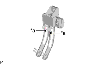
INSTALL FUEL INLET PIPE SUB-ASSEMBLY
Note
When replacing the fuel supply pump assembly, it is necessary to replace the fuel inlet pipe sub-assembly, No. 1 injection pipe clamp and No. 2 injection pipe clamp with a new one. Keep the fuel inlet pipe sub-assembly free of foreign matter.
-
Temporarily install the fuel inlet pipe sub-assembly.
-
Install a new No. 1 injection pipe clamp and No. 2 injection pipe clamp with the 2 bolts.
- Torque:
- 10 N*m { 102 kgf*cm, 7 ft.*lbf }
-
Text in Illustration *a Torque Wrench Fulcrum Length Using SST, tighten the fuel inlet pipe sub-assembly union nut on the common rail side sub-assembly.
- SST
- 09245-11010
- Torque:
- Specified tightening torque
- 40 N*m { 408 kgf*cm, 30 ft.*lbf }
Tech Tips
-
Calculate the torque wrench reading when changing the fulcrum length of the torque wrench.
-
When using a union nut wrench (fulcrum length of 50 mm (1.97 in.)) + torque wrench (fulcrum length of 180 mm (7.09 in.)): 31 N*m (316 kgf*cm, 23 ft.*lbf)
-

Text in Illustration *a Torque Wrench Fulcrum Length Using a 19 mm union nut wrench, tighten the fuel inlet pipe sub-assembly union nut on the fuel supply pump assembly side.
- Torque:
- Specified tightening torque
- 48 N*m { 489 kgf*cm, 35 ft.*lbf }
Tech Tips
-
Calculate the torque wrench reading when changing the fulcrum length of the torque wrench.
-
When using a union nut wrench (fulcrum length of 30 mm (1.18 in.)) + torque wrench (fulcrum length of 180 mm (7.09 in.)): 41 N*m (418 kgf*cm, 30 ft.*lbf)
-
-
INSTALL NO. 1 FUEL HOSE
-
Install the No. 1 fuel hose to the supply pump assembly and No. 2 fuel pipe, and slide the 2 clamps to secure it.
-
-
INSTALL NO. 2 FUEL HOSE
-
Install the No. 2 fuel hose to the supply pump assembly and No. 3 nozzle leakage pipe assembly, and slide the 2 clamps to secure it.
-
-
INSTALL NO. 3 FUEL PIPE
-
INSTALL NO. 4 FUEL PIPE SUB-ASSEMBLY
-
Temporarily install the No. 4 fuel pipe sub-assembly and 2 new gaskets with the 2 union bolts and bolt.
-
Text in Illustration Union Bolt 
Bolt Tighten the union bolt and bolt in the order shown in the illustration.
- Torque:
- union bolt
- 42 N*m { 428 kgf*cm, 31 ft.*lbf }
- bolt
- 10 N*m { 102 kgf*cm, 7 ft.*lbf }
-
Connect the No. 4 fuel pipe sub-assembly to the No. 1 fuel pipe Click here.
-
-
INSTALL FUEL PUMP MOTOR WIRE
-
Connect the fuel pump motor wire connector and install the fuel pump motor wire.
-
-
INSTALL FUEL INJECTION PUMP COVER SUB-ASSEMBLY
-
Install the fuel injection pump cover sub-assembly to the supply pump assembly.
-
-
INSTALL MANIFOLD STAY
-
Install the manifold stay with the 2 bolts.
- Torque:
- 21 N*m { 214 kgf*cm, 15 ft.*lbf }
-
Install the wiring harness clamp bracket with the bolt.
- Torque:
- 13 N*m { 128 kgf*cm, 9 ft.*lbf }
-
-
INSTALL WIRING HARNESS CLAMP BRACKET
-
Install the wiring harness clamp bracket with the bolt.
- Torque:
- 10 N*m { 102 kgf*cm, 7 ft.*lbf }
-
Attach the 2 wire harness clamps.
-
Connect the diesel throttle body assembly connector and pre-stroke control valve connector.
-
-
INSTALL NO. 2 FUEL PIPE
-
Install the No. 2 fuel pipe to the manifold stay with the bolt.
- Torque:
- 10 N*m { 102 kgf*cm, 7 ft.*lbf }
-
Connect the No. 1 fuel hose to the No. 2 fuel pipe, and slide the clamp to secure the hose.
-
-
INSTALL ENGINE OIL LEVEL DIPSTICK GUIDE
-
Apply a light coat of engine oil to a new O-ring and new grommet.
-
Install the O-ring and grommet to the engine oil level dipstick guide.
-
Install the engine oil level dipstick guide with the bolt.
- Torque:
- 10 N*m { 102 kgf*cm, 7 ft.*lbf }
-
Connect the vacuum hose to the intake manifold, and slide the clip to secure the hose.
-
Install the engine oil level dipstick.
-
w/ No. 2 Fuel Pipe Clamp:
Attach the No. 2 fuel pipe clamp to the engine oil level dipstick guide.
-
-
INSTALL NO. 1 EGR COOLER AND NO. 2 EGR VALVE ASSEMBLY WITH ELECTRIC EGR CONTROL VALVE ASSEMBLY
-

Temporarily install the No. 1 EGR cooler and No. 2 EGR valve assembly with electric EGR control valve assembly to the intake manifold with the 4 bolts.
-
Tighten the 4 bolts in the order shown in the illustration.
Tech Tips
Make sure to tighten the bolts in the order.
- Torque:
- 21 N*m { 214 kgf*cm, 15 ft.*lbf }
-
-
INSTALL NO. 4 WATER BY-PASS PIPE SUB-ASSEMBLY
-
Install the No. 4 water by-pass pipe sub-assembly to the intake manifold with the 2 bolts.
- Torque:
- 10 N*m { 102 kgf*cm, 7 ft.*lbf }
-
Connect the water hose to the No. 2 EGR valve assembly, and slide the clamp to secure the hose.
-
Connect the No. 7 water by-pass hose to the No. 4 water by-pass pipe sub-assembly, and slide the clamp to secure the hose.
-
Connect the No. 6 water by-pass hose to the No. 4 water by-pass pipe sub-assembly, and slide the clamp to secure the hose.
-
-
INSTALL VACUUM CONTROL VALVE SET
-
Install the vacuum control valve set to the intake manifold with the 2 bolts.
- Torque:
- 10 N*m { 102 kgf*cm, 7 ft.*lbf }
-
Connect the 2 vacuum hoses to the vacuum control valve set and No. 2 EGR valve assembly.
-
Connect the connector to the vacuum control valve set.
-
-
INSTALL NO. 1 EGR PIPE SUB-ASSEMBLY
-
Using an E8 "TORX" socket wrench, install 2 new stud bolts to the exhaust manifold.
- Torque:
- 10 N*m { 102 kgf*cm, 7 ft.*lbf }
-
Install 2 new gaskets and the No. 1 EGR pipe sub-assembly to the exhaust manifold, electric EGR control valve assembly and No. 1 vacuum transmitting pipe sub-assembly with the bolt and 4 new nuts.
- Torque:
- for bolt
- 10 N*m { 102 kgf*cm, 7 ft.*lbf }
- for nut
- 29 N*m { 296 kgf*cm, 21 ft.*lbf }
-
-
INSTALL CONNECTING WIRE
-
Attach the 2 clamps and install the connecting wire to the bracket.
-
Connect the connector to the common rail assembly.
-
-
INSTALL NO. 3 WATER BY-PASS PIPE SUB-ASSEMBLY
-
Install the No. 3 water by-pass pipe sub-assembly to the No. 1 EGR cooler with the 2 bolts.
- Torque:
- 10 N*m { 102 kgf*cm, 7 ft.*lbf }
-
Connect the No. 8 water by-pass hose to the No. 3 water by-pass pipe sub-assembly, and slide the clamp to secure the hose.
-
Connect the No. 4 fuel hose to the No. 3 water by-pass pipe sub-assembly.
-
-
INSTALL NO. 2 EGR PIPE
-
Install 2 new gaskets and No. 2 EGR pipe to the electric EGR control valve assembly and the intake manifold with the 4 nuts.
- Torque:
- 29 N*m { 296 kgf*cm, 21 ft.*lbf }
-
-
INSTALL EGR VALVE BRACKET
-
Install the EGR valve bracket to the electric EGR control valve assembly and intake manifold with the bolt and nut.
- Torque:
- 21 N*m { 214 kgf*cm, 15 ft.*lbf }
-
-
INSTALL DIESEL TURBO PRESSURE SENSOR
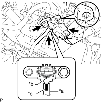
Text in Illustration *1 Diesel Turbo Pressure Sensor *a Vacuum Hose *b Protrusion *c Paint Mark
-
Connect the vacuum hose to the diesel turbo pressure sensor.
Note
Connect the vacuum hose so that the paint mark on the vacuum hose is aligned with the protrusions of the diesel turbo pressure sensor as shown in the illustration.
-
Install the diesel turbo pressure sensor with the bolt.
- Torque:
- 10 N*m { 102 kgf*cm, 7 ft.*lbf }
Note
Make sure the protrusion is inserted into the hole of the diesel turbo pressure sensor.
-
Connect the diesel turbo pressure sensor connector.
-
-
INSTALL ENGINE COVER BRACKET
-
Install the engine cover bracket to the cylinder head cover sub-assembly and hose bracket with the 2 bolts.
- Torque:
- 21 N*m { 214 kgf*cm, 15 ft.*lbf }
-
-
INSTALL PIPE CLAMP
-
Install the pipe clamp to the engine cover bracket with the 3 bolts.
- Torque:
- 10 N*m { 102 kgf*cm, 7 ft.*lbf }
-
-
TEMPORARILY INSTALL NO. 2 VACUUM PIPE
-
Install a new clamp to the pipe clamp.
-
Temporarily install the No. 2 vacuum pipe to the exhaust manifold converter sub-assembly.
-
-
TEMPORARILY INSTALL NO. 1 VACUUM PIPE
-
Temporarily install the No. 1 vacuum pipe to the exhaust manifold converter sub-assembly.
-
Install a new clamp to the No. 1 vacuum pipe and No. 2 vacuum pipe with the nut.
- Torque:
- 6.0 N*m { 61 kgf*cm, 53 in.*lbf }
-
-
TIGHTEN NO. 2 VACUUM PIPE
-
Text in Illustration *a Torque Wrench Fulcrum Length Using a 17 mm union nut wrench, tighten the No. 2 vacuum pipe.
Torque Specified tightening torque 48 N*m {489 kgf*cm, 35 ft.*lbf} Tech Tips
-
Calculate the torque wrench reading when changing the fulcrum length of the torque wrench Click here.
-
When using a union nut wrench (fulcrum length of 30 mm (1.18 in.)) + torque wrench (fulcrum length of 255 mm (10.0 in.)): 43 N*m (437 kgf*cm, 32 ft.*lbf)
-
-
-
TIGHTEN NO. 1 VACUUM PIPE
-
Text in Illustration *a Torque Wrench Fulcrum Length Using a 17 mm union nut wrench, tighten the No. 1 vacuum pipe.
Torque Specified tightening torque 48 N*m {489 kgf*cm, 35 ft.*lbf} Tech Tips
-
Calculate the torque wrench reading when changing the fulcrum length of the torque wrench Click here.
-
When using a union nut wrench (fulcrum length of 30 mm (1.18 in.)) + torque wrench (fulcrum length of 255 mm (10.0 in.)): 43 N*m (437 kgf*cm, 32 ft.*lbf)
-
-
-
INSTALL EXHAUST GAS TEMPERATURE SENSOR
-
Text in Illustration *a Torque Wrench Fulcrum Length Using a 14 mm union nut wrench, install the No. 3 exhaust gas temperature sensor to the exhaust manifold converter sub-assembly.
Torque Specified tightening torque 30 N*m {306 kgf*cm, 22 ft.*lbf} Note
-
If the No. 3 exhaust gas temperature sensor is dropped, replace it with a new.
-
When reusing the No. 3 exhaust gas temperature sensors, clean the screws and apply anti-seize compound before installing the No. 3 exhaust gas temperature sensor.
Tech Tips
-
The connector color of the No. 3 exhaust gas temperature sensor is gray.
-
Calculate the torque wrench reading when changing the fulcrum length of the torque wrench Click here.
-
When using a union nut wrench (fulcrum length of 25 mm (0.984 in.)) + torque wrench (fulcrum length of 180 mm (7.09 in.)): 26 N*m (268 kgf*cm, 19 ft.*lbf)
-
-
Text in Illustration *a Torque Wrench Fulcrum Length Using a 14 mm union nut wrench, install the No. 2 exhaust gas temperature sensor to the exhaust manifold converter sub-assembly.
Torque Specified tightening torque 30 N*m {306 kgf*cm, 22 ft.*lbf} Note
-
If the No. 2 exhaust gas temperature sensor is dropped, replace it with a new.
-
When reusing the No. 2 exhaust gas temperature sensors, clean the screws and apply anti-seize compound before installing the No. 2 exhaust gas temperature sensor.
Tech Tips
-
The connector color of the No. 2 exhaust gas temperature sensor is black.
-
Calculate the torque wrench reading when changing the fulcrum length of the torque wrench Click here.
-
When using a union nut wrench (fulcrum length of 25 mm (0.984 in.)) + torque wrench (fulcrum length of 180 mm (7.09 in.)): 26 N*m (268 kgf*cm, 19 ft.*lbf)
-
-
Text in Illustration *a Torque Wrench Fulcrum Length Using a 14 mm union nut wrench, install the exhaust gas temperature sensor to the exhaust manifold converter sub-assembly.
Torque Specified tightening torque 30 N*m {306 kgf*cm, 22 ft.*lbf} Note
-
If the exhaust gas temperature sensor is dropped, replace it with a new.
-
When reusing the exhaust gas temperature sensors, clean the screws and apply anti-seize compound before installing the exhaust gas temperature sensor.
Tech Tips
-
The connector color of the exhaust gas temperature sensor is white.
-
Calculate the torque wrench reading when changing the fulcrum length of the torque wrench Click here.
-
When using a union nut wrench (fulcrum length of 25 mm (0.984 in.)) + torque wrench (fulcrum length of 180 mm (7.09 in.)): 26 N*m (268 kgf*cm, 19 ft.*lbf)
-
-
Text in Illustration *a White *b Black *c Gray Attach the 3 colored connectors to the pipe clamp in the positions shown in the illustration.
-
Close the clamp of the pipe clamp, and install the bolt.
- Torque:
- 10 N*m { 102 kgf*cm, 7 ft.*lbf }
Note
Arrange the exhaust gas temperature sensor wires so that they do not contact each other.
-
Connect the No. 3 exhaust gas temperature sensor to the No. 1 vacuum pipe.
- Torque:
- 10 N*m { 102 kgf*cm, 7 ft.*lbf }
-
Connect the 3 connectors to the 3 exhaust gas temperature sensors.
-
-
INSTALL DIFFERENTIAL PRESSURE SENSOR
-
Text in Illustration *a Paint Mark Install the 2 air hoses to the differential pressure sensor, and slide the 2 clamps to secure the 2 hoses.
Tech Tips
Make sure the paint mark of the air hose side the differential pressure sensor.
-
Connect the 2 air hoses to the No. 1 vacuum pipe and No. 2 vacuum pipe, and slide the 2 clamps to secure the 2 hoses.
-
Install the differential pressure sensor to the pipe clamp with the bolt.
- Torque:
- 10 N*m { 102 kgf*cm, 7 ft.*lbf }
-
Connect the connector to the differential pressure sensor.
-
-
INSTALL NO. 2 WATER BY-PASS PIPE
-
Install the No. 2 water by-pass pipe with the 2 bolts.
- Torque:
- 10 N*m { 102 kgf*cm, 7 ft.*lbf }
-
-
INSTALL DIESEL THROTTLE BODY ASSEMBLY
-
Connect the connector to install the emission control valve wire to the diesel throttle body assembly.
-
Install a new gasket and the diesel throttle body assembly with the 2 bolts and 2 nuts.
- Torque:
- 10 N*m { 102 kgf*cm, 7 ft.*lbf }
-
Connect the connector and clamp.
-
-
INSTALL GAS FILTER BRACKET
-
Install the gas filter bracket to the diesel throttle body assembly with the bolt.
- Torque:
- 10 N*m { 102 kgf*cm, 7 ft.*lbf }
-
-
INSTALL GAS FILTER
-
Install the gas filter to the gas filter bracket.
-
Connect the 2 vacuum hoses to the turbo pressure sensor and intake manifold.
-
-
INSTALL INTERCOOLER AIR TUBE
-
Install the intercooler air tube to the diesel throttle body assembly and tighten the hose clamp.
- Torque:
- 6.0 N*m { 61 kgf*cm, 53 in.*lbf }
-
Connect the connector to the intake air temperature sensor.
-
Install the air tube support bracket with the 3 bolts.
- Torque:
- 6.0 N*m { 61 kgf*cm, 53 in.*lbf }
-
-
INSTALL ENGINE WIRE