TOYOTA PARKING ASSIST-SENSOR SYSTEM Parking Brake Switch Circuit
| DTC Code | DTC Name |
|---|---|
| Parking Brake Switch Circuit |
DESCRIPTION
This circuit includes the parking brake switch and the clearance warning ECU.
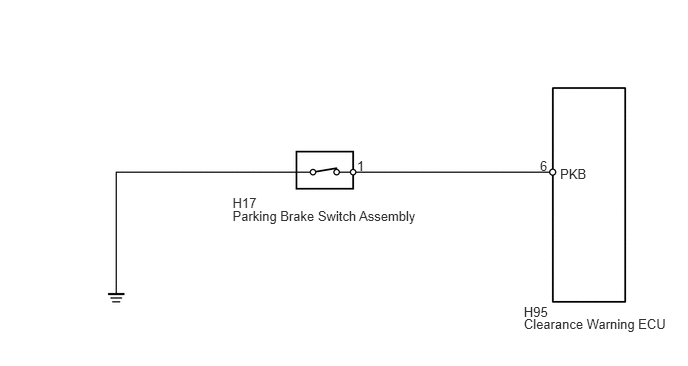
WIRING DIAGRAM
PROCEDURE
CHECK HARNESS AND CONNECTOR (CLEARANCE WARNING ECU - PARKING BRAKE SWITCH)
Disconnect the H95 clearance warning ECU connector.
Disconnect the H17 parking brake switch assembly connector.
Measure the resistance according to the value(s) in the table below.
Standard Resistance
Tester Connection
Condition
Specified Condition
H95-6 (PKB) - H17-1
Always
Below 1 Ω
H95-6 (PKB) - Body ground
Always
10 kΩ or higher
REPAIR OR REPLACE HARNESS OR CONNECTOR
INSPECT PARKING BRAKE SWITCH ASSEMBLY
-
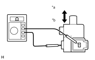
Remove the parking brake switch assembly (Click here).
Measure the resistance according to the value(s) in the table below.
Standard Resistance
Tester Connection
Switch Condition
Specified Condition
Switch connector terminal - Switch body
ON (Shaft not pressed)
Below 1 Ω
OFF (Shaft pressed)
10 kΩ or higher
Table 1. Text in Illustration *a
ON
*b
OFF
-