LIGHTING SYSTEM TERMINALS OF ECU
CHECK HEADLIGHT SWIVEL ECU ASSEMBLY

Disconnect the A46 headlight swivel ECU connector.
Measure the resistance and voltage according to the value(s) in the table below.
Terminal No. (Symbol)
Wiring Color
Terminal Description
Condition
Specified Condition
A46-22 (E1) - Body ground
W-B - Body ground
Headlight swivel ECU ground
Always
Below 1 Ω
A46-14 (IGS) - Body ground
L - Body ground
Swivel motor power supply
Engine switch off
Below 1 V
Engine switch on (IG)
11 to 14 V
A46-15 (IG) - Body ground
G - Body ground
Headlight swivel ECU power supply
Engine switch off
Below 1 V
Engine switch on (IG)
11 to 14 V
If the result is not as specified, there may be a malfunction on the wire harness side.
Reconnect the A46 headlight swivel ECU connector.
Measure the resistance and voltage according to the value(s) in the table below.
Terminal No. (Symbol)
Wiring Color
Terminal Description
Condition
Specified Condition
A46-21 (SGF) - A46-22 (E1)
W - W-B
Rear height control sensor ground
Always
Below 1 Ω
A46-23 (SMGL) - A46-22 (E1)
G - W-B
Swivel motor LH ground
Always
Below 1 Ω
A46-24 (SMGR) - A46-22 (E1)
P - W-B
Swivel motor RH ground
Always
Below 1 Ω
A46-27 (LH-) - A46-22 (E1)
LG - W-B
Leveling motor LH ground
Always
Below 1 Ω
A46-28 (RH-) - A46-22 (E1)
LG - W-B
Leveling motor RH ground
Always
Below 1 Ω
A46-1 (SMBL) - A46-22 (E1)
V - W-B
Swivel motor LH power supply
Engine switch off
Below 1 V
Engine switch on (IG)
11 to 16 V
A46-2 (SMBR) - A46-22 (E1)
B - W-B
Swivel motor RH power supply
Engine switch off
Below 1 V
Engine switch on (IG)
11 to 16 V
A46-3 (LHT) - A46-22 (E1)
L - W-B
Leveling motor LH power supply
Engine switch off
Below 1 V
Engine switch on (IG)
11 to 16 V
A46-4 (RHT) - A46-22 (E1)
GR - W-B
Leveling motor RH power supply
Engine switch off
Below 1 V
Engine switch on (IG)
11 to 16 V
A46-7 (INIT) - A46-22 (E1)
R - W-B
Initialization signal
Engine switch on (IG), terminals LVL and GND of DLC3 connected
Below 1 V
Engine switch on (IG), terminals LVL and GND of DLC3 not connected
Approximately 5 V
A46-10 (SMR) - A46-22 (E1)
L - W-B
Swivel motor RH LIN communication
Engine switch off
Below 1 V
Engine switch on (IG)
Pulse generation
(See waveform 1)
A46-11 (RH+) - A46-22 (E1)
R - W-B
Leveling motor RH LIN communication
Engine switch off
Below 1 V
Engine switch on (IG)
Pulse generation
(See waveform 1)
A46-18 (SBF) - A46-21 (SGF)
R-G - W
Rear height control sensor power supply
Engine switch off
Below 1 V
Engine switch on (IG)
Approximately 5 V
A46-19 (SHRL) - A46-21 (SGF)
B-R - W
Rear height control sensor signal
Engine switch off
Below 1 V
Engine switch on (IG)
1 to 4 V
A46-29 (SML) - A46-22 (E1)
W - W-B
Swivel motor LH LIN communication
Engine switch off
Below 1 V
Engine switch on (IG)
Pulse generation
(See waveform 1)
A46-30 (LH+) - A46-22 (E1)
R - W-B
Leveling motor LH LIN communication
Engine switch off
Below 1 V
Engine switch on (IG)
Pulse generation
(See waveform 1)
If the result is not as specified, the headlight swivel ECU may have a malfunction.
-
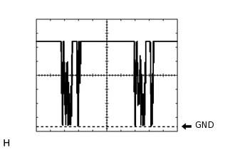
Waveform 1
Item
Content
Terminal No. (Symbol)
A46-10 (SMR) - A46-22 (E1)
A46-11 (RH+) - A46-22 (E1)
A46-29 (SML) - A46-22 (E1)
A46-30 (LH+) - A46-22 (E1)
Tool setting
2 V/DIV., 20 ms./DIV.
Condition
Engine switch on (IG)
-
CHECK DRIVER SIDE JUNCTION BLOCK ASSEMBLY, MAIN BODY ECU (MULTIPLEX NETWORK BODY ECU)
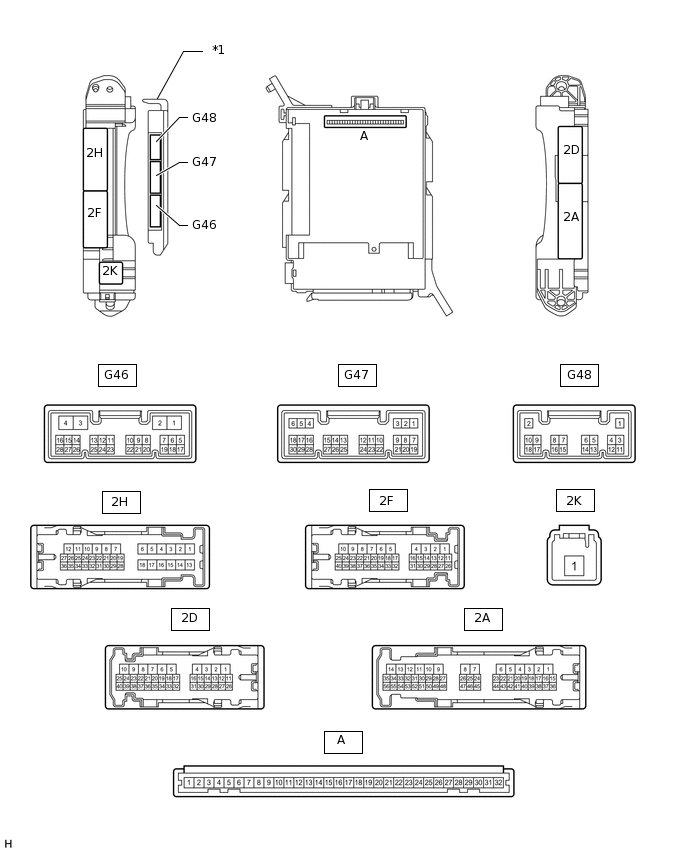
*1
Main body ECU (Multiplex Network Body ECU)
-
-
Remove the main body ECU (Click here).
Measure the resistance and voltage according to the value(s) in the table below.
Terminal No. (Symbol)
Wiring Color
Terminal Description
Condition
Specified Condition
A-29 (ACC) - Body ground
-
ACC power supply
Engine switch on (ACC)
11 to 14 V
A-30 (BECU) - Body ground
-
Battery power supply
Always
11 to 14 V
A-32 (IG) - Body ground
-
Ignition power supply
Engine switch on (IG)
11 to 14 V
A-11 (GND1) - Body ground
-
Ground
Always
Below 1 Ω
G46-3 (GND2) - Body ground
W-B - Body ground
Ground
Always
Below 1 Ω
If the result is not as specified, there may be a malfunction on the wire harness side.
Install the main body ECU (Click here).
Measure the voltage according to the value(s) in the table below.
Terminal No. (Symbol)
Wiring Color
Terminal Description
Condition
Specified Condition
G46-23 (RFOG) - 2D-4 (GND1)*
SB - W-B
Rear fog light switch input
Rear fog light switch on
Below 1 V
Rear fog light switch off
11 to 14 V
G47-1 (GCTY) - 2D-4 (GND1)
V - W-B
Glass hatch courtesy light switch signal
Glass hatch open
Below 1 V
Glass hatch closed
Pulse generation
(See waveform 1 or 2)
G47-3 (HAZ) - 2D-4 (GND1)
W - W-B
Hazard warning signal switch output
Hazard warning signal switch on
Below 1 V
Hazard warning signal switch off
11 to 14 V
G47-5 (HU) - 2D-4 (GND1)
LG - W-B
Headlight dimmer switch high signal input
Headlight dimmer switch in head and high
Below 1 V
Headlight dimmer switch in head and low
Pulse generation
(See waveform 3 or 4)
G47-6 (RCTY) - 2D-4 (GND1)
R - W-B
Rear door courtesy light switch RH signal
Rear door RH open
Below 1 V
Rear door RH closed
11 to 14 V
G47-8 (HF) - 2D-4 (GND1)
V - W-B
Headlight dimmer switch high flash signal input
Headlight dimmer switch in high flash position
Below 1 V
Headlight dimmer switch not in high flash position
11 to 14 V
G47-15 (DIM) - 2D-4 (GND1)
P - W-B
Running light relay drive output
Headlight dimmer switch in head and high or high flash
Below 1 V
Headlight dimmer switch not in head and high or high flash
11 to 14 V
G47-19 (BCTY) - 2D-4 (GND1)
G - W-B
Back door courtesy light switch signal
Back door open
Below 1 V
Back door closed
(See waveform 5 or 6)
G47-20 (CLTB) - 2D-4 (GND1)
P - W-B
Automatic light control sensor power supply output
Engine switch off
Below 1 V
Engine switch on (IG) and headlight dimmer switch in AUTO position
11 to 14 V
G47-21 (CLTS) - 2D-4 (GND1)
R - W-B
Automatic light control sensor signal input
Engine switch off
Below 1 V
Engine switch on (IG)
Headlight dimmer switch AUTO
Automatic light control sensor covered with a hand → Automatic light control sensor exposed to ambient light
Pulse generation
(See waveform 11)
G47-27 (FFOG) - 2D-4 (GND1)
G - W-B
Front fog light switch input
Front fog light switch on
Below 1 V
Front fog light switch off
Pulse generation
(See waveform 7 or 8)
G47-28 (A) - 2D-4 (GND1)
W - W-B
Headlight dimmer switch AUTO signal input
Headlight dimmer switch in AUTO
Below 1 V
Headlight dimmer switch not in AUTO
Pulse generation
(See waveform 9 or 10)
G47-29 (HEAD) - 2D-4 (GND1)
SB - W-B
Headlight dimmer switch head signal input
Headlight dimmer switch in head
Below 1 V
Headlight dimmer switch not in head
11 to 14 V
G47-30 (TAIL) - 2D-4 (GND1)
W - W-B
Headlight dimmer switch tail signal input
Headlight dimmer switch in tail or head
Below 1 V
Headlight dimmer switch in neither tail nor head
11 to 14 V
G48-3 (LCTY) - 2D-4 (GND1)
V - W-B
Rear door courtesy light switch LH signal
Rear door LH open
Below 1 V
Rear door LH closed
11 to 14 V
2F-24 (DRL) - 2D-4 (GND1)
P - W-B
DRL relay drive output
Daytime running light on
Below 1 V
Daytime running light off
11 to 14 V
2D-15 (FRCY) - 2D-4 (GND1)
B - W-B
Front door courtesy light switch RH signal
Front door RH open
Below 1 V
Front door RH closed
11 to 14 V
2F-7 (TRLY) - 2D-4 (GND1)
LG - W-B
Clearance light signal output
Headlight dimmer switch in tail position
11 to 14 V
Headlight dimmer switch not in tail position
Below 1 V
2F-9 (FFGO) - 2D-4 (GND1)
W - W-B
Front fog light signal output
Headlight dimmer switch in tail and front fog light switch on
11 to 14 V
Front fog light switch off
Below 1 V
2F-19 (RFGO) - 2D-4 (GND1)*
GR-L - W-B
Rear fog light signal output
Headlight dimmer switch in tail and rear fog light switch on
11 to 14 V
Rear fog light switch off
Below 1 V
2F-40 (HRLY) - 2D-4 (GND1)
GR - W-B
H-LP LO relay drive output
Headlight dimmer switch in head
Below 1 V
Headlight dimmer switch not in head
11 to 14 V
2H-16 (TRLY) - 2D-4 (GND1)
LG - W-B
Taillight and license plate light signal output
Headlight dimmer switch in tail position
11 to 14 V
Headlight dimmer switch not in tail position
Below 1 V
2H-27 (FLCY) - 2D-4 (GND1)
R - W-B
Front door courtesy light switch LH signal
Front door LH open
Below 1 V
Front door LH closed
11 to 14 V
2K-1 (TRLY) - 2D-4 (GND1)
B - W-B
Battery power supply
Always
11 to 14 V
*: w/ Rear Fog Light
If the result is not as specified, the main body ECU may have a malfunction.
-
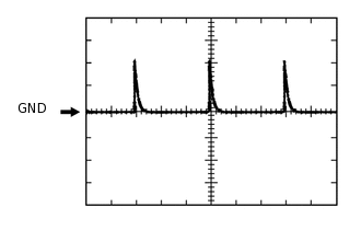
Waveform 1
Item
Content
Terminal No. (Symbol)
G47-1 (GCTY) - 2D-4 (GND1)
Tool setting
5 V/DIV., 20 ms./DIV.
Condition
Glass hatch closed
-
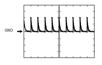
Waveform 2
Item
Content
Terminal No. (Symbol)
G47-1 (GCTY) - 2D-4 (GND1)
Tool setting
5 V/DIV., 20 ms./DIV.
Condition
Glass hatch closed
-
Waveform 3
Item
Content
Terminal No. (Symbol)
G47-5 (HU) - 2D-4 (GND1)
Tool setting
5 V/DIV., 20 ms./DIV.
Condition
Headlight dimmer switch in head and low
-
Waveform 4
Item
Content
Terminal No. (Symbol)
G47-5 (HU) - 2D-4 (GND1)
Tool setting
5 V/DIV., 20 ms./DIV.
Condition
Headlight dimmer switch in head and low
-
Waveform 5
Item
Content
Terminal No. (Symbol)
G47-19 (BCTY) - 2D-4 (GND1)
Tool setting
5 V/DIV., 20 ms./DIV.
Condition
Back door closed
-
Waveform 6
Item
Content
Terminal No. (Symbol)
G47-19 (BCTY) - 2D-4 (GND1)
Tool setting
5 V/DIV., 20 ms./DIV.
Condition
Back door closed
-
Waveform 7
Item
Content
Terminal No. (Symbol)
G47-27 (FFOG) - 2D-4 (GND1)
Tool setting
5 V/DIV., 20 ms./DIV.
Condition
Front fog light switch off
-
Waveform 8
Item
Content
Terminal No. (Symbol)
G47-27 (FFOG) - 2D-4 (GND1)
Tool setting
5 V/DIV., 20 ms./DIV.
Condition
Front fog light switch off
-
Waveform 9
Item
Content
Terminal No. (Symbol)
G47-28 (A) - 2D-4 (GND1)
Tool setting
5 V/DIV., 20 ms./DIV.
Condition
Headlight dimmer switch not in AUTO
-
Waveform 10
Item
Content
Terminal No. (Symbol)
G47-28 (A) - 2D-4 (GND1)
Tool setting
5 V/DIV., 20 ms./DIV.
Condition
Headlight dimmer switch not in AUTO
-
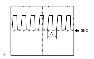
Waveform 11
Item
Content
Terminal No. (Symbol)
G47-21 (CLTS) - 2D-4 (GND1)
Tool setting
5 V/DIV., 5 ms./DIV.
Condition
Engine switch on (IG)
Headlight dimmer switch AUTO
Automatic light control sensor covered with a hand → Automatic light control sensor exposed to ambient light
Tip:When the ambient light becomes brighter, width A becomes narrower.