ENGINE UNIT
-
CONSTRUCTION
-
The cylinder head structure is simplified by separating the cam journal portion (camshaft housing sub-assembly) from the cylinder head sub-assembly.
-
The cylinder head sub-assembly, which is made of aluminum, contains pentroof-type combustion chambers. The spark plug is located in the center of the combustion chamber in order to improve the engine's anti-knock performance.
-
A taper squish combustion chamber is used to improve anti-knock performance and intake efficiency. In addition, engine performance and fuel economy are improved.
-
A long-nozzle type fuel injector assembly for port injection, which has a protruding design, is used to optimize the intake airflow. Also, the fuel injection angle and port shape are optimized in consideration of reducing fuel adhesion to achieve low fuel consumption and low emissions.
-
The shape of the intake port has been optimized, thus increasing the tumble flow and flow of air into the combustion chamber, and improving engine power and fuel economy.
-
The shape of the exhaust port has been optimized, thus making it easier for the engine to expel burnt gas, and improving engine power.
-
The valve lash adjuster assemblies are installed in the upper part of the cylinder head sub-assembly, creating a structure where the oil passage supplying oil to the valve lash adjuster assemblies are combined with the interior of the cylinder head sub-assembly.
-
The diameter of the intake and exhaust valve has increased, thus improving engine power.
-
The shape of the water jacket is optimized to reduce the temperature of combustion chamber components and minimize the temperature difference between cylinders. These two improvements achieve a high compression ratio, which achieves high torque, high engine output and low fuel consumption.
-
A sub-water jacket is used around the exhaust ports to improve the following:
-
Heater performance due to warm-up improvements
-
Fuel economy due to reduced friction
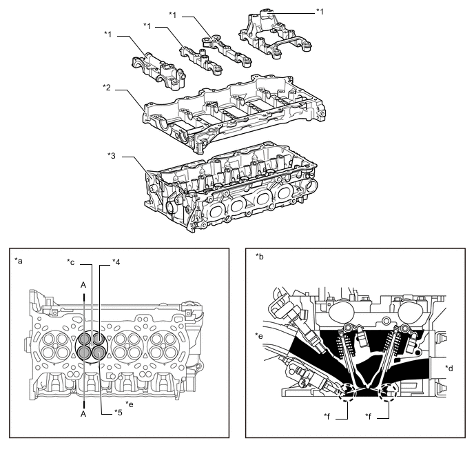
*1 Camshaft Bearing Cap *2 Camshaft Housing Sub-assembly *3 Cylinder Head Sub-assembly *4 Exhaust Valve *5 Intake Valve - - *a View from Bottom Side *b A-A Cross Section *c Spark Plug Hole *d Exhaust Side *e Intake Side *f Taper Squish -
-