CAMSHAFT REMOVAL
PROCEDURE
REMOVE INLET NO. 1 AIR CLEANER
REMOVE AIR CLEANER CAP SUB-ASSEMBLY
REMOVE AIR CLEANER FILTER ELEMENT SUB-ASSEMBLY
REMOVE NO. 1 IGNITION COIL
SEPARATE DUTY VACUUM SWITCHING VALVE
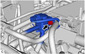
Remove the bolt and separate the duty vacuum switching valve from the cylinder head cover sub-assembly.
SEPARATE ENGINE WIRE
Separate the engine wire from the cylinder head cover sub-assembly.
REMOVE CYLINDER HEAD COVER SUB-ASSEMBLY
REMOVE CYLINDER HEAD COVER GASKET
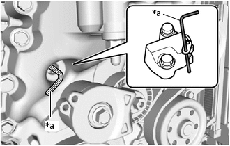
REMOVE TIMING GEAR COVER TIGHT PLUG
-
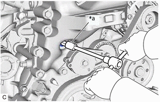
*a
8 mm Hexagon Socket Wrench
Using an 8 mm hexagon socket wrench, remove the timing gear cover tight plug.
-
SET NO. 1 CYLINDER TO TDC/EXHAUST
-
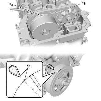
*a
Timing Mark
Turn the crankshaft pulley clockwise to align the timing mark of the pulley with the timing mark of the timing chain cover sub-assembly (set the No. 1 piston to TDC/exhaust).
-
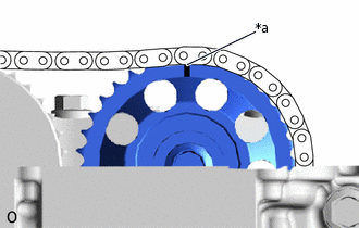
*a
Timing Mark
Make sure that the timing mark of the camshaft timing gear is at the top.
Tip:If the timing mark is not at the top, turn the crankshaft pulley 1 revolution so that the timing mark comes to the top (set the No. 1 piston to TDC/exhaust).
-
REMOVE CAMSHAFT TIMING GEAR
-
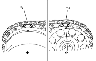
*a
Paint Mark
*b
Timing Mark
Place paint marks on the chain plates in alignment with the timing marks of the camshaft timing gear and camshaft timing sprocket assembly.
Rotate the crankshaft 90° clockwise.
Note:Do not allow a lifted valve and piston to come into contact with each other when removing the camshaft.
-
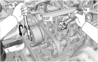
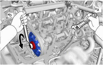
*a
Hold
*b
Turn
Using SST, loosen the bolts of the camshaft timing sprocket assembly while holding the hexagonal portion of the camshaft.
09249-37010
-
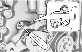
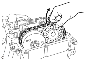
*a
Stopper Plate
*b
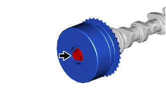
Plunger
Insert a screwdriver into the plug hole and turn the stopper plate of the No. 1 chain tensioner assembly clockwise to release the lock.
Tip:The plunger of the No. 1 chain tensioner assembly is locked.
If the stopper plate is locked firmly, slightly turn the hexagonal portion of the camshaft to the right and left.
-
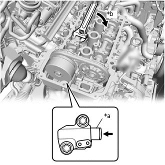
*a
Plunger
*b
Turn
While ensuring that the lock remains released, slightly turn the hexagonal portion of the camshaft clockwise so that the plunger of the No. 1 chain tensioner assembly is pushed by the chain sub-assembly.
-
*a
Hexagon Wrench
Insert a hexagon wrench into the stopper plate hole.
Tip:Hold the hexagon wrench with tape so that the hexagon wrench does not come off.
-
*a
Hold
*b
Turn
Remove the bolt of the camshaft timing gear while holding the hexagonal portion of the No. 2 camshaft.
-
Remove the camshaft timing gear.
-
REMOVE CAMSHAFT
-
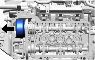
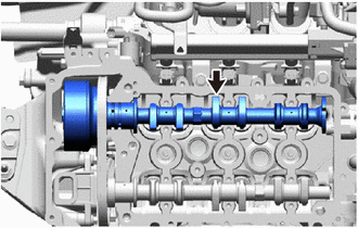
Slide the camshaft timing sprocket assembly toward the front of the engine until the No. 1 camshaft bearing cap comes off.
-
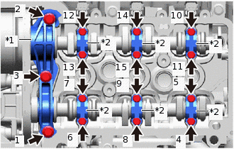
*1
No. 1 Camshaft Bearing Cap
*2
No. 2 Camshaft Bearing Cap
Remove the 15 bolts in the order shown in the illustration.
Remove the No. 1 camshaft bearing cap and No. 2 camshaft bearing caps.
-
Remove the camshaft.
Tip:Remove the camshaft with the camshaft timing sprocket assembly.
-
REMOVE NO. 2 CAMSHAFT
-
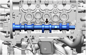
Remove the No. 2 camshaft.
-
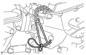
Using a piece of string or equivalent, secure the chain sub-assembly to prevent it from dropping.
-
REMOVE CAMSHAFT TIMING SPROCKET ASSEMBLY
-
Remove the bolt and camshaft timing sprocket assembly.
-
INSPECT CAMSHAFT TIMING SPROCKET ASSEMBLY