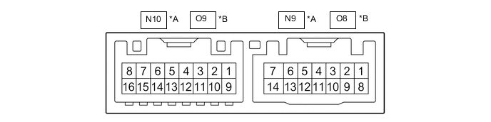
POWER MIRROR CONTROL SYSTEM(w/ Memory) TERMINALS OF ECU
-
CHECK OUTER MIRROR CONTROL ECU ASSEMBLY (DRIVER DOOR)

*A for LHD *B for RHD
-
Disconnect the O8*1 or N9*2 outer mirror control ECU assembly (driver door) connector.
-
*1: for LHD
-
*2: for RHD
-
-
Measure the voltage and resistance according to the value(s) in the table below.
Tech Tips
Measure the values on the wire harness side with the connector disconnected.
for LHD: Terminal No. (Symbol) Wiring Color Terminal Description Condition Specified Condition O8-14 (BDR) - Body ground GR - Body ground +B power supply Always 11 to 14 V O8-6 (CPUB) - Body ground LA-L - Body ground +B power supply Always 11 to 14 V O8-5 (SIG) - Body ground LA-B - Body ground Ignition power supply Engine switch off → on (IG) Below 1 V → 11 to 14 V O8-7 (GND) - Body ground W-B - Body ground Ground Always Below 1 Ω for RHD: Terminal No. (Symbol) Wiring Color Terminal Description Condition Specified Condition N9-14 (BDR) - Body ground GR - Body ground +B power supply Always 11 to 14 V N9-6 (CPUB) - Body ground LA-L - Body ground +B power supply Always 11 to 14 V N9-5 (SIG) - Body ground LA-B - Body ground Ignition power supply Engine switch off → on (IG) Below 1 V → 11 to 14 V N9-7 (GND) - Body ground W-B - Body ground Ground Always Below 1 Ω -
Reconnect the O8*1 or N9*2 outer mirror control ECU assembly (driver door) connector.
-
*1: for LHD
-
*2: for RHD
-
-
Measure the voltage according to the value(s) in the table below.
for LHD: Terminal No. (Symbol) Wiring Color Terminal Description Condition Specified Condition O9-3 (MR+) - Body ground B - Body ground Power retract mirror motor drive voltage Outer rear view mirror assembly (driver door) being retracted 11 to 14 V Outer rear view mirror assembly (driver door) stopped Below 1 V O9-11 (MR-) - Body ground L - Body ground Power retract mirror motor drive voltage Outer rear view mirror assembly (driver door) returning 11 to 14 V Outer rear view mirror assembly (driver door) stopped Below 1 V O9-1 (LMVR) - O9-10 (LM+R) BR - V Vertical mirror motor drive voltage Driver door mirror surface moving upward → stopped 11 to 14 V → Below 1 V O9-10 (LM+R) - O9-1 (LMVR) V - BR Vertical mirror motor drive voltage Driver door mirror surface moving downward → stopped 11 to 14 V → Below 1 V O9-10 (LM+R) - O9-9 (LMHR) V - LG Horizontal mirror motor drive voltage Driver door mirror surface moving right → stopped 11 to 14 V → Below 1 V O9-9 (LMHR) - O9-10 (LM+R) LG - V Horizontal mirror motor drive voltage Driver door mirror surface moving left → stopped 11 to 14 V → Below 1 V O9-4 (HTR+) - O9-12 (HTR-) LG - W Mirror heater relay drive voltage Mirror heater switch (rear window defogger switch) on 11 to 14 V O9-5 (LVC) - O9-14 (LE1) G - BR Mirror position sensor power supply Engine switch on (IG) 4.55 to 5.45 V Engine switch off Below 1 V O9-6 (VSSR) - O8-7 (GND) V - W-B Mirror position sensor signal Engine switch on (IG) 0 to 5 V O9-13 (HSSR) - O8-7 (GND) GR - W-B Mirror position sensor signal Engine switch on (IG) 0 to 5 V O8-3 (M2) - O8-7 (GND) R - W-B M2 switch signal for seat memory switch M2 switch on Below 1 V M2 switch off 11 to 14 V O8-2 (M1) - O8-7 (GND) BR - W-B M1 switch signal for seat memory switch M1 switch on Below 1 V M1 switch off 11 to 14 V O8-1 (MM) - O8-7 (GND) GR - W-B SET switch signal for seat memory switch SET switch on Below 1 V SET switch off 11 to 14 V for RHD: Terminal No. (Symbol) Wiring Color Terminal Description Condition Specified Condition N10-1 (RMVR) - N10-10 (RM+R) BR - V Vertical mirror motor drive voltage Driver door mirror surface moving upward → stopped 11 to 14 V → Below 1 V N10-10 (RM+R) - N10-1 (RMVR) V - BR Vertical mirror motor drive voltage Driver door mirror surface moving downward → stopped 11 to 14 V → Below 1 V N10-10 (RM+R) - N10-9 (RMHR) V - LG Horizontal mirror motor drive voltage Driver door mirror surface moving right → stopped 11 to 14 V → Below 1 V N10-9 (RMHR) - N10-10 (RM+R) LG - V Horizontal mirror motor drive voltage Driver door mirror surface moving left → stopped 11 to 14 V → Below 1 V N10-5 (RVC) - N10-14 (RE1) G - BR Mirror position sensor power supply Engine switch on (IG) 4.55 to 5.45 V Engine switch off Below 1 V N10-6 (VSSR) - N9-7 (GND) V - W-B Mirror position sensor signal Engine switch on (IG) 0 to 5 V N10-13 (HSSR) - N9-7 (GND) GR - W-B Mirror position sensor signal Engine switch on (IG) 0 to 5 V N9-3 (M2) - N9-7 (GND) R - W-B M2 switch signal for seat memory switch M2 switch on Below 1 V M2 switch off 11 to 14 V N9-2 (M1) - N9-7 (GND) BR - W-B M1 switch signal for seat memory switch M1 switch on Below 1 V M1 switch off 11 to 14 V N9-1 (MM) - N9-7 (GND) GR - W-B SET switch signal for seat memory switch SET switch on Below 1 V SET switch off 11 to 14 V
-
-
CHECK OUTER MIRROR CONTROL ECU ASSEMBLY (FRONT PASSENGER DOOR)
*A for LHD *B for RHD
-
Disconnect the N9*1 or O8*2 outer mirror control ECU assembly (front passenger door) connector.
-
*1: for LHD
-
*2: for RHD
-
-
Measure the voltage and resistance according to the value(s) in the table below.
Tech Tips
Measure the values on the wire harness side with the connector disconnected.
for LHD: Terminal No. (Symbol) Wiring Color Terminal Description Condition Specified Condition N9-14 (BDR) - Body ground GR - Body ground +B power supply Always 11 to 14 V N9-6 (CPUB) - Body ground LA-L - Body ground +B power supply Always 11 to 14 V N9-5 (SIG) - Body ground LA-B - Body ground Ignition power supply Engine switch off → on (IG) Below 1 V → 11 to 14 V N9-7 (GND) - Body ground W-B - Body ground Ground Always Below 1 Ω for RHD: Terminal No. (Symbol) Wiring Color Terminal Description Condition Specified Condition O8-14 (BDR) - Body ground GR - Body ground +B power supply Always 11 to 14 V O8-6 (CPUB) - Body ground LA-L - Body ground +B power supply Always 11 to 14 V O8-5 (SIG) - Body ground LA-B - Body ground Ignition power supply Engine switch off → on (IG) Below 1 V → 11 to 14 V O8-7 (GND) - Body ground W-B - Body ground Ground Always Below 1 Ω -
Reconnect the N9*1 or O8*2 outer mirror control ECU assembly (front passenger door) connector.
-
*1: for LHD
-
*2: for RHD
-
-
Measure the voltage according to the value(s) in the table below.
for LHD: Terminal No. (Symbol) Wiring Color Terminal Description Condition Specified Condition N10-3 (MR+) - Body ground B - Body ground Power retract mirror motor drive voltage Outer rear view mirror assembly (front passenger door) being retracted 11 to 14 V Outer rear view mirror assembly (front passenger door) stopped Below 1 V N10-11 (MR-) - Body ground P - Body ground Power retract mirror motor drive voltage Outer rear view mirror assembly (front passenger door) returning 11 to 14 V Outer rear view mirror assembly (front passenger door) stopped Below 1 V N10-1 (RMVR) - N10-10 (RM+R) BR - V Vertical mirror motor drive voltage Front passenger door mirror surface moving upward → stopped 11 to 14 V → Below 1 V N10-10 (RM+R) - N10-1 (RMVR) V - BR Vertical mirror motor drive voltage Front passenger door mirror surface moving downward → stopped 11 to 14 V → Below 1 V N10-10 (RM+R) - N10-9 (RMHR) V - LG Horizontal mirror motor drive voltage Front passenger door mirror surface moving right → stopped 11 to 14 V → Below 1 V N10-9 (RMHR) - N10-10 (RM+R) LG - V Horizontal mirror motor drive voltage Front passenger door mirror surface moving left → stopped 11 to 14 V → Below 1 V N10-4 (HTR+) - N10-12 (HTR-) LG - W Mirror heater relay drive voltage Mirror heater switch (rear window defogger switch) on 11 to 14 V N10-5 (RVC) - N10-14 (RE1) G - BR Mirror position sensor power supply Engine switch on (IG) 4.55 to 5.45 V Engine switch off Below 1 V N10-6 (VSSR) - N9-7 (GND) V - W-B Mirror position sensor signal Engine switch on (IG) 0 to 5 V N10-13 (HSSR) - N9-7 (GND) GR - W-B Mirror position sensor signal Engine switch on (IG) 0 to 5 V for RHD: Terminal No. (Symbol) Wiring Color Terminal Description Condition Specified Condition O9-1 (LMVR) - O9-10 (LM+R) BR - V Vertical mirror motor drive voltage Front passenger door mirror surface moving upward → stopped 11 to 14 V → Below 1 V O9-10 (LM+R) - O9-1 (LMVR) V - BR Vertical mirror motor drive voltage Front passenger door mirror surface moving downward → stopped 11 to 14 V → Below 1 V O9-10 (LM+R) - O9-9 (LMHR) V - LG Horizontal mirror motor drive voltage Front passenger door mirror surface moving right → stopped 11 to 14 V → Below 1 V O9-9 (LMHR) - O9-10 (LM+R) LG - V Horizontal mirror motor drive voltage Front passenger door mirror surface moving left → stopped 11 to 14 V → Below 1 V O9-5 (LVC) - O9-14 (LE1) G - BR Mirror position sensor power supply Engine switch on (IG) 4.55 to 5.45 V Engine switch off Below 1 V O9-6 (VSSR) - O8-7 (GND) V - W-B Mirror position sensor signal Engine switch on (IG) 0 to 5 V O9-13 (HSSR) - O8-7 (GND) GR - W-B Mirror position sensor signal Engine switch on (IG) 0 to 5 V
-
-
CHECK MAIN BODY ECU (MULTIPLEX NETWORK BODY ECU) AND INSTRUMENT PANEL JUNCTION BLOCK ASSEMBLY
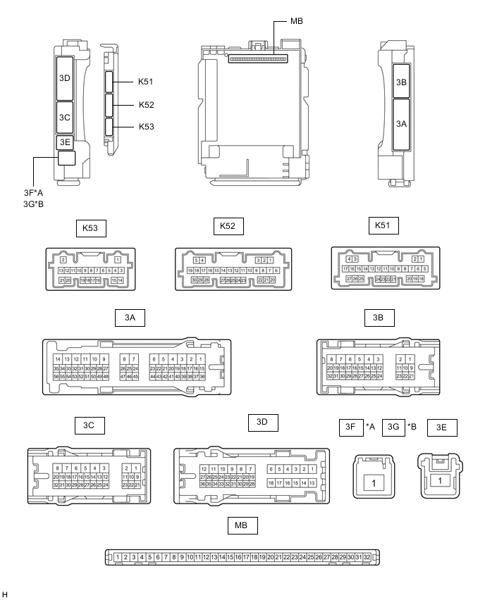
*A for LHD *B for RHD
-
Disconnect the instrument panel junction block assembly and main body ECU (multiplex network body ECU) connectors.
-
Reconnect the instrument panel junction block assembly connectors.
-
Measure the voltage and resistance according to the value(s) in the table below.
Tech Tips
Measure the values on the wire harness side with the connector disconnected.
Terminal No. (Symbol) Wiring Color Terminal Description Condition Specified Condition MB-31 (BECU) - Body ground - Battery power supply Always 11 to 14 V MB-32 (IG) - Body ground - Ignition power supply (IG signal) Engine switch on (IG) 11 to 14 V Engine switch off Below 1 V MB-30 (ACC) - Body ground - Ignition power supply (ACC signal) Engine switch on (ACC) 11 to 14 V Engine switch off Below 1 V MB-11 (GND1) - Body ground - Ground Always Below 1 Ω -
Connect the main body ECU (multiplex network body ECU) connectors.
-
Measure the voltage according to the value(s) in the table below.
for LHD: Tester Connection Wiring Color Terminal Description Condition Specified Condition K53-7 (MIRB) - K53-9 (MIRE) L - W Mirror surface adjust switch signal
-
Engine switch on (ACC)
-
Mirror surface adjust switch up
Below 1.7 V
-
Engine switch on (ACC)
-
Mirror surface adjust switch right
Below 2.7 V
-
Engine switch on (ACC)
-
Mirror surface adjust switch down
Below 3.5 V
-
Engine switch on (ACC)
-
Mirror surface adjust switch left
Below 4 V
-
Engine switch on (ACC)
-
Mirror surface adjust switch off
3.8 to 5 V K53-8 (MIRS) - K53-9 (MIRE) GR - W Mirror select switch signal
-
Engine switch on (ACC)
-
Mirror select switch L
Below 2 V
-
Engine switch on (ACC)
-
Mirror select switch R
Below 1 V
-
Engine switch on (ACC)
-
Mirror select switch off
3.8 to 5.0 V K53-16 (RET) - K53-9 (MIRE) B - W Mirror retract switch signal
-
Engine switch on (ACC)
-
Mirror retract switch not in return position
Pulse generation (See waveform 1 or 2)
-
Engine switch on (ACC)
-
Mirror retract switch in return position
Below 1 V K53-6 (AMR) - K53-9 (MIRE) BE - W Mirror retract switch signal
-
Engine switch on (ACC)
-
Mirror retract switch not in retract position
Pulse generation (See waveform 1 or 2)
-
Engine switch on (ACC)
-
Mirror retract switch in retract position
Below 1 V -
-
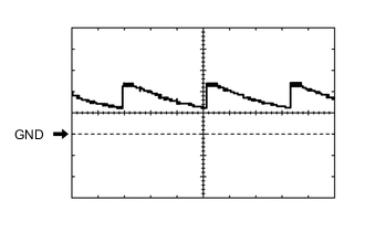
Using an oscilloscope, check waveform 1.
Waveform 1 (Reference) Item Content Tester Connection K53-16 (RET) or K53-6 (AMR) - K53-9 (MIRE) Tool Setting 5 V/DIV., 20 ms/DIV. Condition
-
Engine switch on (ACC)
-
Retractable outer mirror switch not in return position
-
-
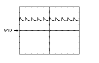
Using an oscilloscope, check waveform 2.
Waveform 2 (Reference) Item Content Tester Connection K53-16 (RET) or K53-6 (AMR) - K53-9 (MIRE) Tool Setting 5 V/DIV., 20 ms/DIV. Condition
-
Engine switch on (ACC)
-
Retractable outer mirror switch not in retract position
for RHD: Tester Connection Wiring Color Terminal Description Condition Specified Condition K53-7 (MIRB) - K53-9 (MIRE) L - W Mirror surface adjust switch signal
-
Engine switch on (ACC)
-
Mirror surface adjust switch up
Below 1.7 V
-
Engine switch on (ACC)
-
Mirror surface adjust switch right
Below 2.7 V
-
Engine switch on (ACC)
-
Mirror surface adjust switch down
Below 3.5 V
-
Engine switch on (ACC)
-
Mirror surface adjust switch left
Below 4 V
-
Engine switch on (ACC)
-
Mirror surface adjust switch off
3.8 to 5 V K53-8 (MIRS) - K53-9 (MIRE) GR - W Mirror select switch signal
-
Engine switch on (ACC)
-
Mirror select switch L
Below 2 V
-
Engine switch on (ACC)
-
Mirror select switch R
Below 1 V
-
Engine switch on (ACC)
-
Mirror select switch off
3.8 to 5.0 V -
-