LIGHTING SYSTEM Interior Light Auto Cut Circuit
DESCRIPTION
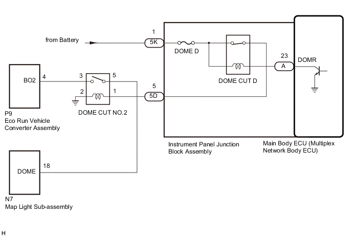
When the battery saving control operates, the main body ECU (multiplex network body ECU) controls the operation of the DOME CUT D relay that is built into the instrument panel junction block assembly to turn off the interior lights.
WIRING DIAGRAM
CAUTION / NOTICE / HINT
Note
-
Inspect the fuses for circuits related to this system before performing the following procedure.
-
Before replacing the main body ECU (multiplex network body ECU), refer to Service Bulletin.
PROCEDURE
-
PERFORM ACTIVE TEST USING GTS
-
Perform the Active Test according to the display on the GTS.
Body Electrical > Main Body > Active TestTester Display Measurement Item Control Range Diagnostic Note Relay for Interior Light Auto Cut Function DOME CUT D relay ON or OFF When performing this Active Test, turn all the interior lights on.
-
OFF: DOME CUT D relay on (interior lights turn on)
-
ON: DOME CUT D relay off (interior lights turn off)
Body Electrical > Main Body > Active TestTester Display Relay for Interior Light Auto Cut Function OK All of the interior lights turn off when ON is selected. Result Proceed to OK NG -
OK 
PROCEED TO NEXT SUSPECTED AREA SHOWN IN PROBLEM SYMPTOMS TABLE Click here
NG 
-
-
CHECK MAP LIGHT SUB-ASSEMBLY
-
Disconnect the N7 map light sub-assembly connector.
-
Measure the voltage according to the value(s) in the table below.
Standard Voltage Tester Connection Condition Specified Condition N7-18 (DOME) - Body ground Always 10.5 to 16 V Result Proceed to OK NG
OK
REPLACE MAP LIGHT SUB-ASSEMBLY Click here
NG
-
-
INSPECT DOME CUT NO.2 RELAY
-
Remove the DOME CUT NO.2 relay from No. 2 luggage room relay block assembly.
-
Inspect the DOME CUT NO.2 relay.
Result Proceed to OK NG
NG
REPLACE DOME CUT NO.2 RELAY
OK
-
-
CHECK HARNESS AND CONNECTOR (DOME CUT NO.2 RELAY - BATTERY)
-
Remove the DOME CUT NO.2 relay from No. 2 luggage room relay block assembly.
-
Measure the voltage according to the value(s) in the table below.
Standard Voltage Tester Connection Condition Specified Condition DOME CUT NO.2 relay terminal 3 - Body ground Always 11 to 14 V Result Proceed to OK NG
NG 
CHECK HARNESS AND CONNECTOR (DOME CUT NO.2 RELAY - ECO RUN VEHICLE CONVERTER ASSEMBLY) Click here
OK
-
-
CHECK HARNESS AND CONNECTOR (DOME CUT NO.2 RELAY - INSTRUMENT PANEL JUNCTION BLOCK ASSEMBLY AND BODY GROUND)
-
Remove the DOME CUT NO.2 relay from No. 2 luggage room relay block assembly.
-
Disconnect the 5D strument panel junction block assembly connector.
-
Measure the resistace according to the value(s) in the table below.
Standard Resistace Tester Connection Condition Specified Condition DOME CUT NO.2 relay terminal 1 - 5D-5 Always Below 1 Ω DOME CUT NO.2 relay terminal 2 - Body ground Always Below 1 Ω DOME CUT NO.2 relay terminal 1 or 5D-5 - Body ground Always 10 kΩ or higher Result Proceed to OK NG
NG
REPAIR OR REPLACE HARNESS OR CONNECTOR
OK
-
-
CHECK HARNESS AND CONNECTOR (INSTRUMENT PANEL JUNCTION BLOCK ASSEMBLY - BATTERY)
-
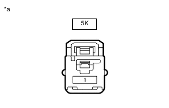
*a Front view of wire harness connector
(to Instrument Panel Junction Block Assembly)
Disconnect the instrument panel junction block assembly connector.
-
Measure the voltage according to the value(s) in the table below.
Standard Voltage Tester Connection Condition Specified Condition 5K-1 - Body ground Always 11 to 14 V Result Proceed to OK NG
NG
REPAIR OR REPLACE HARNESS OR CONNECTOR
OK
-
-
CHECK INSTRUMENT PANEL JUNCTION BLOCK ASSEMBLY
-
Remove the instrument panel junction block assembly.
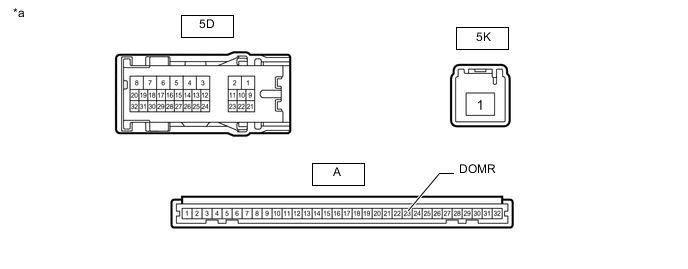
*a Component without harness connected
(Instrument Panel Junction Block Assembly)
- - -
Remove the main body ECU (multiplex network body ECU) from the instrument panel junction block assembly.
-
Measure the resistance according to the value(s) in the table below.
Standard Resistance Tester Connection Condition Specified Condition 5K-1 - 5D-5 Battery not connected to 5K-1 and A-23 (DOMR) Below 1 Ω -
Measure the voltage according to the value(s) in the table below.
Standard Voltage Tester Connection Condition Specified Condition 5D-5 - Battery negative (-) terminal Battery positive (+) → 5K-1
Battery negative (-) → A-23 (DOMR)
Below 1 V Result Proceed to OK NG
OK
REPLACE MAIN BODY ECU (MULTIPLEX NETWORK BODY ECU) Click here
NG
REPLACE INSTRUMENT PANEL JUNCTION BLOCK ASSEMBLY Click here
-
-
CHECK HARNESS AND CONNECTOR (DOME CUT NO.2 RELAY - ECO RUN VEHICLE CONVERTER ASSEMBLY)
-
Remove the DOME CUT NO.2 relay from No. 2 luggage room relay block assembly.
-
Disconnect the P9 eco run vehicle converter assembly connector.
-
Measure the resistace according to the value(s) in the table below.
Standard Resistace Tester Connection Condition Specified Condition DOME CUT NO.2 relay terminal 3 - P9-4 (BO2) Always Below 1 Ω DOME CUT NO.2 relay terminal 3 or P9-4 (BO2) - Body ground Always 10 kΩ or higher Result Proceed to OK NG
OK
REPLACE ECO RUN VEHICLE CONVERTER ASSEMBLY Click here
NG
REPAIR OR REPLACE HARNESS OR CONNECTOR
-