STARTER (for 1.0 kW Type) REASSEMBLY
Tech Tips
Use high temperature-resistant grease to lubricate the bearings and sliding parts when assembling the starter.
-
INSTALL PLANETARY CARRIER SHAFT SUB-ASSEMBLY
-
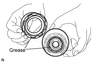
Apply high-temperature grease to the part of the internal gear that contacts the shock absorber and planetary gears, and the part of the shock absorber that contacts the internal gear.
-
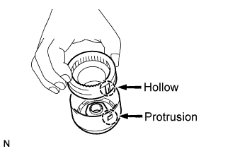
Align the hollow of the internal gear with the protrusion inside the shock absorber.
-
Inset and turn the internal gear so that it interlocks with the shock absorber.
-
Apply high-temperature grease to the plate washer, and install it to the planetary shaft.
-
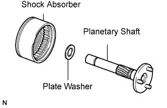
Install the planetary shaft to the internal gear with shock absorber.
-
Apply high-temperature grease to the center bearing.
-
Install the center bearing.
-
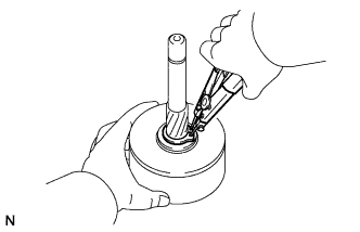
Using snap ring pliers, install the plate washer and snap ring.
-
-
INSTALL STARTER CLUTCH SUB-ASSEMBLY
-
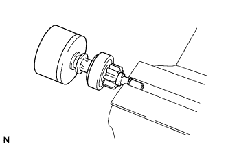
Apply high-temperature grease to the spline of the starter clutch and the stop collar.
-
Place the starter clutch and stop collar on the planetary shaft.
-
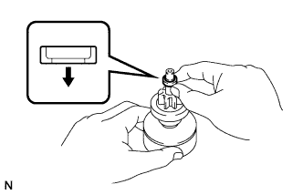
Apply high-temperature grease to the snap ring, and install it to the planetary shaft groove.
-
Using a vise, compress the snap ring between aluminum plates.
-
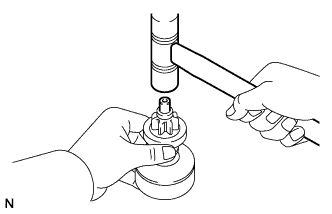
Holding the starter clutch, tap the planetary shaft with a plastic-faced hammer to install the stop collar onto the snap ring.
-
-
INSTALL PLANETARY GEAR
-
Apply high-temperature grease to the planetary gears and flange pins of the planetary shaft.
-
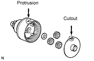
Install the plate washer and 3 planetary gears.
-
Align the cutout of the plate with the protrusion inside the shock absorber, and install the plate.
-
-
INSTALL DRIVE LEVER AND STARTER CLUTCH WITH SHOCK ABSORBER
-
Apply high-temperature grease to the bearing of the starter drive housing.
-
Apply high-temperature grease to the starter drive lever as shown in the illustration.
-
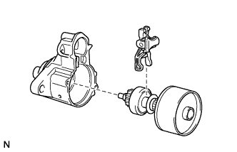
Install the starter drive lever to the starter clutch sub-assembly.
-
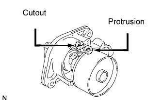
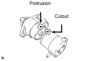
Align the protrusion of the shock absorber with the cutout of the starter drive housing and install the drive lever and starter clutch with shock absorber.
-
-
INSTALL STARTER BRUSH HOLDER ASSEMBLY
-
Install the starter armature to the starter yoke.
-
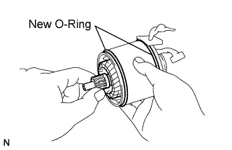
Install 2 new O-rings to the starter yoke.
-
Install the brush holder to the armature.
-
Install the 4 starter brushes to the starter brush holder.
-
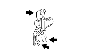
Using a screwdriver, pull back the spring.
-
Install the brush to the brush holder.
Note
Check that positive (+) lead wires are not grounded.
-
-
-
INSTALL STARTER COMMUTATOR END FRAME ASSEMBLY
-
Apply high-temperature grease to the bearing of the end frame.
-
Install the end frame with the 2 screws.
- Torque:
- 1.5 N*m { 15 kgf*cm, 13 in.*lbf }
-
-
INSTALL STARTER YOKE ASSEMBLY
-
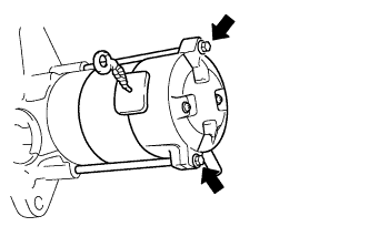
Align the cutout of the starter yoke with the protrusion of the shock absorber.
-
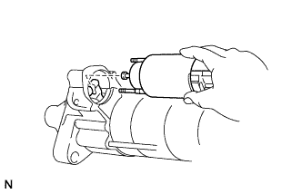
Install the starter yoke with armature with the 2 through bolts.
- Torque:
- 5.9 N*m { 60 kgf*cm, 52 in.*lbf }
-
-
INSTALL MAGNET STARTER SWITCH ASSEMBLY
-
Install the plunger cover to the magnet starter switch assembly.
-
Attach the plunger of the magnet starter switch assembly to the drive lever from the upper side.
-
Install the magnet starter switch assembly with the 2 nuts.
- Torque:
- 8.3 N*m { 85 kgf*cm, 73 in.*lbf }
-
Connect the lead wire to the terminal, and install the nut.
- Torque:
- 9.8 N*m { 100 kgf*cm, 87 in.*lbf }
-