LIGHTING SYSTEM Door Courtesy Light Circuit
DESCRIPTION
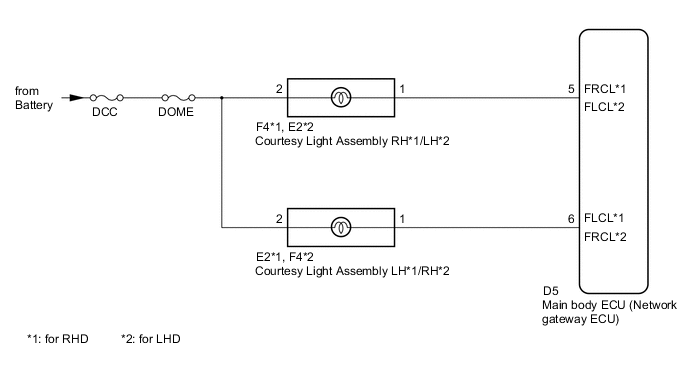
The main body ECU (network gateway ECU) controls the operation of the courtesy light assembly.
WIRING DIAGRAM
CAUTION / NOTICE / HINT
Tech Tips
Inspect the fuses and bulbs for circuits related to this system before performing the following inspection procedure.
PROCEDURE
-
PERFORM ACTIVE TEST USING GTS
-
Connect the GTS to the DLC3.
-
Turn the ignition switch to ON.
-
Turn the GTS on.
-
Enter the following menus: Body Electrical / Main Body / Active Test.
-
Check that the lights operate.
OK Each light comes on. Main Body Tester Display Test Part Control Range Diagnostic Note Driver Courtesy Lamp Driver courtesy light ON/OFF - Passenger Courtesy Lamp Passenger courtesy light ON/OFF - Result Result Proceed to All lights do not come on A Courtesy light assembly RH does not come on B Courtesy light assembly LH does not come on C
A 
PROCEED TO NEXT SUSPECTED AREA SHOWN IN PROBLEM SYMPTOMS TABLE Click here
C 
CHECK HARNESS AND CONNECTOR (BATTERY - COURTESY LIGHT) Click here
B 
-
-
CHECK HARNESS AND CONNECTOR (BATTERY - COURTESY LIGHT)
-
Disconnect the F4 courtesy light assembly RH connector.
-
Measure the voltage according to the value(s) in the table below.
Standard Voltage Tester Connection Condition Specified Condition F4-2 - Body ground Always 11 to 14 V
NG
REPAIR OR REPLACE HARNESS OR CONNECTOR
OK
-
-
INSPECT COURTESY LIGHT ASSEMBLY
-
Remove the courtesy light assembly RH Click here.
-
Inspect the courtesy light assembly RH Click here.
OK Courtesy light assembly RH is normal.
NG
REPLACE COURTESY LIGHT ASSEMBLY Click here
OK
-
-
CHECK HARNESS AND CONNECTOR (MAIN BODY ECU (NETWORK GATEWAY ECU) - COURTESY LIGHT AND BODY GROUND)
-
Disconnect the D5 main body ECU (network gateway ECU) connector.
-
Disconnect the F4 courtesy light assembly RH connector.
-
Measure the resistance according to the value(s) in the table below.
Standard Resistance for RHD Tester Connection Condition Specified Condition D5-5 (FRCL) - F4-1 Always Below 1 Ω F4-1 - Body ground Always 10 kΩ or higher Standard Resistance for LHD Tester Connection Condition Specified Condition D5-6 (FRCL) - F4-1 Always Below 1 Ω F4-1 - Body ground Always 10 kΩ or higher
OK
REPLACE MAIN BODY ECU (NETWORK GATEWAY ECU) Click here
NG
REPAIR OR REPLACE HARNESS OR CONNECTOR
-
-
CHECK HARNESS AND CONNECTOR (BATTERY - COURTESY LIGHT)
-
Disconnect the E2 courtesy light assembly LH connector.
-
Measure the voltage according to the value(s) in the table below.
Standard Voltage Tester Connection Condition Specified Condition E2-2 - Body ground Always 11 to 14 V
NG
REPAIR OR REPLACE HARNESS OR CONNECTOR
OK
-
-
INSPECT COURTESY LIGHT ASSEMBLY
-
Remove the courtesy light assembly LH Click here.
-
Inspect the courtesy light assembly LH Click here.
OK Courtesy light assembly LH is normal.
NG
REPLACE COURTESY LIGHT ASSEMBLY Click here
OK
-
-
CHECK HARNESS AND CONNECTOR (MAIN BODY ECU (NETWORK GATEWAY ECU) - COURTESY LIGHT AND BODY GROUND)
-
Disconnect the D5 main body ECU (network gateway ECU) connector.
-
Disconnect the E2 courtesy light assembly LH connector.
-
Measure the resistance according to the value(s) in the table below.
Standard Resistance for RHD Tester Connection Condition Specified Condition D5-6 (FLCL) - E2-1 Always Below 1 Ω E2-1 - Body ground Always 10 kΩ or higher Standard Resistance for LHD Tester Connection Condition Specified Condition D5-5 (FLCL) - E2-1 Always Below 1 Ω E2-1 - Body ground Always 10 kΩ or higher
OK
REPLACE MAIN BODY ECU (NETWORK GATEWAY ECU) Click here
NG
REPAIR OR REPLACE HARNESS OR CONNECTOR
-