CONTINUOUSLY VARIABLE TRANSAXLE SYSTEM Shift Paddle Switch Circuit
DESCRIPTION
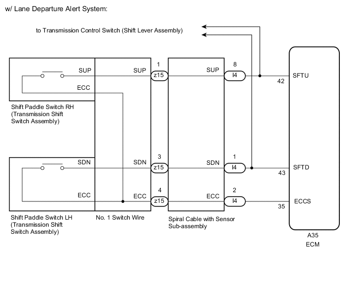
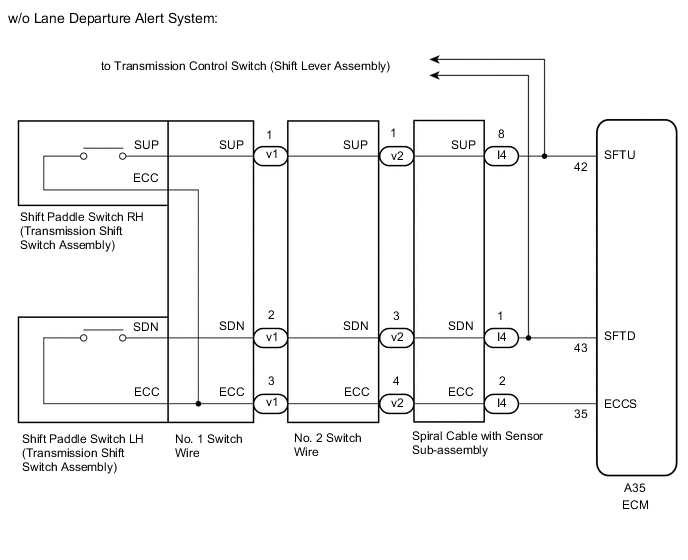
When the shift lever is in M, the shift range can be changed using the shift paddle switches. It is also possible to select the shift range when the vehicle is being driven with the shift lever in D by operating the shift paddle switches.
WIRING DIAGRAM
CAUTION / NOTICE / HINT
Note
-
Perform initialization when parts related to the continuously variable transaxle are replaced.
-
Check that no DTCs are stored after performing initialization.
PROCEDURE
-
READ VALUE USING GTS (SPORTS SHIFT UP SW AND SPORTS SHIFT DOWN SW)
-
Connect the GTS to the DLC3.
-
Turn the engine switch on (IG).
-
Turn the GTS on.
-
Enter the following menus: Powertrain / Engine and ECT / Data List
-
According to the display on the GTS, read the Data List.
Powertrain > Engine and ECT > Data ListTester Display Measurement Item Range Normal Condition Diagnostic Note Sports Shift Up SW Sport shift up switch status ON or OFF
-
ON: "+" shift paddle operated and held (up-shift)
-
OFF: "+" shift paddle not operated (up-shift)
- Sports Shift Down SW Sport shift down switch status ON or OFF
-
ON: "-" shift paddle operated and held (down-shift)
-
OFF: "-" shift paddle not operated (down-shift)
-
Powertrain > Engine and ECT > Data ListTester Display Sports Shift Up SW Sports Shift Down SW Result Result Proceed to Data display is within Normal Condition range A Data display is not within Normal Condition range B -
A 
CHECK FOR INTERMITTENT PROBLEMS Click here
B 
-
-
INSPECT TRANSMISSION SHIFT SWITCH ASSEMBLY (SHIFT PADDLE SWITCH)
-
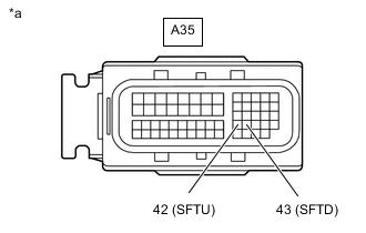
*a Front view of wire harness connector
(to ECM)
Disconnect the ECM connector.
-
Measure the resistance according to the value(s) in the table below.
Standard Resistance Tester Connection Condition Specified Condition A35-42 (SFTU) - Body ground "+" shift paddle operated and held (up-shift) Below 2.5 Ω A35-42 (SFTU) - Body ground "+" shift paddle not operated (up-shift) 1 MΩ or higher A35-43 (SFTD) - Body ground "-" shift paddle operated and held (down-shift) Below 2.5 Ω A35-43 (SFTD) - Body ground "-" shift paddle not operated (down-shift) 1 MΩ or higher Result Proceed to OK NG
OK
GO TO TRANSMISSION CONTROL SWITCH CIRCUIT Click here
NG
-
-
CHECK HARNESS AND CONNECTOR (SPIRAL CABLE WITH SENSOR SUB-ASSEMBLY - BODY GROUND)
-
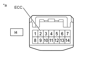
*a Front view of wire harness connector
(to Spiral Cable with Sensor Sub-assembly)
Disconnect the spiral cable with sensor sub-assembly connector.
-
Measure the resistance according to the value(s) in the table below.
Standard Resistance Tester Connection Condition Specified Condition I4-2 (ECC) - Body ground Always Below 1 Ω Result Proceed to OK NG
NG 
CHECK HARNESS AND CONNECTOR (SPIRAL CABLE WITH SENSOR SUB-ASSEMBLY - ECM) Click here
OK
-
-
CHECK HARNESS AND CONNECTOR (SPIRAL CABLE WITH SENSOR SUB-ASSEMBLY - ECM)
-
Disconnect the I4 spiral cable with sensor sub-assembly connector.
-
Disconnect the A35 ECM connector.
-
Measure the resistance according to the value(s) in the table below.
Standard Resistance Tester Connection Condition Specified Condition I4-1 (SDN) - A35-43 (SFTD) Always Below 1 Ω I4-8 (SUP) - A35-42 (SFTU) Always Below 1 Ω I4-1 (SDN) or A35-43 (SFTD) - Body ground Always 10 kΩ or higher I4-8 (SUP) or A35-42 (SFTU) - Body ground Always 10 kΩ or higher Result Proceed to OK NG
NG
REPAIR OR REPLACE HARNESS OR CONNECTOR
OK
-
-
INSPECT SPIRAL CABLE WITH SENSOR SUB-ASSEMBLY
-
Inspect the spiral cable with sensor sub-assembly.
Result Proceed to OK NG
NG
REPLACE SPIRAL CABLE WITH SENSOR SUB-ASSEMBLY Click here
OK
-
-
INSPECT SHIFT PADDLE SWITCH LH (TRANSMISSION SHIFT SWITCH ASSEMBLY)
-
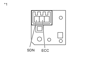
*1 Shift Paddle Switch LH Remove the shift paddle switch LH.
-
Measure the resistance according to the value(s) in the table below.
Standard Resistance Tester Connection Condition Specified Condition SDN - ECC "-" shift paddle operated and held (down-shift) Below 2.5 Ω SDN - ECC "-" shift paddle not operated (down-shift) 1 MΩ or higher Result Proceed to OK NG
NG
REPLACE SHIFT PADDLE SWITCH LH (TRANSMISSION SHIFT SWITCH ASSEMBLY) Click here
OK
-
-
INSPECT SHIFT PADDLE SWITCH RH (TRANSMISSION SHIFT SWITCH ASSEMBLY)
-
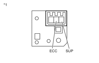
*1 Shift Paddle Switch RH Remove the shift paddle switch RH.
-
Measure the resistance according to the value(s) in the table below.
Standard Resistance Tester Connection Condition Specified Condition SUP - ECC "+" shift paddle operated and held (up-shift) Below 2.5 Ω SUP - ECC "+" shift paddle not operated (up-shift) 1 MΩ or higher Result Result Proceed to OK (w/ Lane Departure Alert System) A OK (w/o Lane Departure Alert System) B NG C
B
INSPECT NO. 1 SWITCH WIRE Click here
C
REPLACE SHIFT PADDLE SWITCH RH (TRANSMISSION SHIFT SWITCH ASSEMBLY) Click here
A
-
-
INSPECT NO. 1 SWITCH WIRE
-
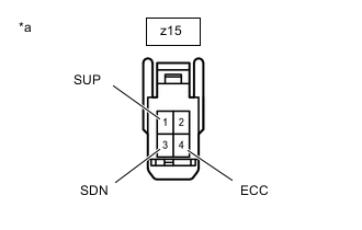
*a No. 1 switch wire
(to Spiral Cable with Sensor Sub-assembly)
Disconnect the No. 1 switch wire connector.
-
Measure the resistance according to the value(s) in the table below.
Standard Resistance Tester Connection Condition Specified Condition z15-3 (SDN) - z15-4 (ECC) "-" shift paddle operated and held (down-shift) Below 2.5 Ω z15-3 (SDN) - z15-4 (ECC) "-" shift paddle not operated (down-shift) 1 MΩ or higher z15-1 (SUP) - z15-4 (ECC) "+" shift paddle operated and held (up-shift) Below 2.5 Ω z15-1 (SUP) - z15-4 (ECC) "+" shift paddle not operated (up-shift) 1 MΩ or higher Result Proceed to OK NG
NG
REPLACE NO. 1 SWITCH WIRE Click here
OK
-
-
REPLACE ECM
-
Replace the ECM.
Result Proceed to NEXT
NEXT
PERFORM INITIALIZATION Click here
-
-
INSPECT NO. 1 SWITCH WIRE
-
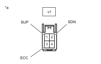
*a No. 1 switch wire
(to No. 2 switch wire)
Disconnect the No. 1 switch wire connector.
-
Measure the resistance according to the value(s) in the table below.
Standard Resistance Tester Connection Condition Specified Condition v1-2 (SDN) - v1-3 (ECC) "-" shift paddle operated and held (down-shift) Below 2.5 Ω v1-2 (SDN) - v1-3 (ECC) "-" shift paddle not operated (down-shift) 1 MΩ or higher v1-1 (SUP) - v1-3 (ECC) "+" shift paddle operated and held (up-shift) Below 2.5 Ω v1-1 (SUP) - v1-3 (ECC) "+" shift paddle not operated (up-shift) 1 MΩ or higher Result Proceed to OK NG
NG
REPLACE NO. 1 SWITCH WIRE Click here
OK
-
-
INSPECT NO. 2 SWITCH WIRE
-
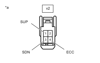
*a No. 2 switch wire
(to Spiral Cable with Sensor Sub-assembly)
Disconnect the No. 2 switch wire connector.
-
Measure the resistance according to the value(s) in the table below.
Standard Resistance Tester Connection Condition Specified Condition v2-3 (SDN) - v2-4 (ECC) "-" shift paddle operated and held (down-shift) Below 2.5 Ω v2-3 (SDN) - v2-4 (ECC) "-" shift paddle not operated (down-shift) 1 MΩ or higher v2-1 (SUP) - v2-4 (ECC) "+" shift paddle operated and held (up-shift) Below 2.5 Ω v2-1 (SUP) - v2-4 (ECC) "+" shift paddle not operated (up-shift) 1 MΩ or higher Result Proceed to OK NG
NG
REPLACE NO. 2 SWITCH WIRE Click here
OK
-
-
REPLACE ECM
-
Replace the ECM.
Result Proceed to NEXT
NEXT
PERFORM INITIALIZATION Click here
-
-
CHECK HARNESS AND CONNECTOR (SPIRAL CABLE WITH SENSOR SUB-ASSEMBLY - ECM)
-
Disconnect the I4 spiral cable with sensor sub-assembly connector.
-
Disconnect the A35 ECM connector.
-
Measure the resistance according to the value(s) in the table below.
Standard Resistance Tester Connection Condition Specified Condition I4-2 (ECC) - A35-35 (ECCS) Always Below 1 Ω I4-2 (ECC) or A35-35 (ECCS) - Body ground Always 10 kΩ or higher Result Proceed to OK NG
NG
REPAIR OR REPLACE HARNESS OR CONNECTOR
OK
-
-
REPLACE ECM
-
Replace the ECM.
Result Proceed to NEXT
NEXT
PERFORM INITIALIZATION Click here
-