AUDIO AND VISUAL SYSTEM(w/o Multi-display), Diagnostic DTC:74-40
| DTC Code | DTC Name |
|---|---|
| 74-40 | Short in Speaker Circuit |
DESCRIPTION
DTC No. |
Detection Item |
DTC Detection Condition |
Trouble Area |
|---|---|---|---|
74-40 |
Short in Speaker Circuit |
A short is detected in the speaker output circuit. |
|
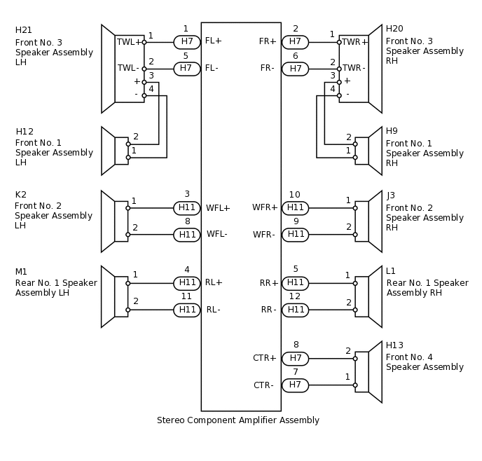
WIRING DIAGRAM
CAUTION / NOTICE / HINT
After the inspection is completed, clear the DTCs.
PROCEDURE
CHECK FOR DTC
Disconnect the H7 and H11 stereo component amplifier assembly connectors.
Clear the DTC.
Check if DTC 74-40 is output.
OK
No DTC is output.
Result
Result
OK
NG
CHECK FOR DTC
Reconnect the H11 stereo component amplifier assembly connector.
Check if DTC 74-40 is output.
OK
No DTC is output.
Result
Result
OK
NG
NG CHECK HARNESS AND CONNECTOR (STEREO COMPONENT AMPLIFIER - SPEAKER)Click here
CHECK HARNESS AND CONNECTOR (STEREO COMPONENT AMPLIFIER - SPEAKER)
Disconnect the H7 stereo component amplifier assembly connector.
Disconnect the H20*1 and/or H21*2 front No. 3 speaker assembly connector.
*1: for RH
*2: for LH
Disconnect the H13 front No. 4 speaker assembly connector.
Measure the resistance according to the value(s) in the table below.
Standard Resistance
Tester Connection
Condition
Specified Condition
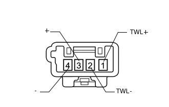
H7-1 (FL+) - H21-1 (TWL+)
Always
Below 1 Ω
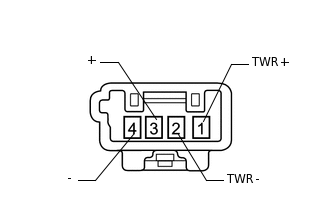
H7-2 (FR+) - H20-1 (TWR+)
Always
Below 1 Ω
H7-5 (FL-) - H21-2 (TWL-)
Always
Below 1 Ω
H7-6 (FR-) - H20-2 (TWR-)
Always
Below 1 Ω
H7-7 (CTR-) - H13-1
Always
Below 1 Ω
H7-8 (CTR+) - H13-2
Always
Below 1 Ω
H7-1 (FL+) - Body ground
Always
10 kΩ or higher
H7-2 (FR+) - Body ground
Always
10 kΩ or higher
H7-5 (FL-) - Body ground
Always
10 kΩ or higher
H7-6 (FR-) - Body ground
Always
10 kΩ or higher
H7-7 (CTR-) - Body ground
Always
10 kΩ or higher
H7-8 (CTR+) - Body ground
Always
10 kΩ or higher
Result
Result
OK
NG
NG REPAIR OR REPLACE HARNESS OR CONNECTOR
INSPECT FRONT NO. 3 SPEAKER ASSEMBLY RH
-
Disconnect the H20 front No. 3 speaker assembly RH connector.
Measure the resistance according to the value(s) in the table below.
Standard Resistance
Tester Connection
Condition
Specified Condition
1 (TWR+) - 3 (+)
Always
Below 1 Ω
2 (TWR-) - 4 (-)
Always
Below 1 Ω
Result
Result
OK
NG
-
INSPECT FRONT NO. 1 SPEAKER ASSEMBLY RH
-
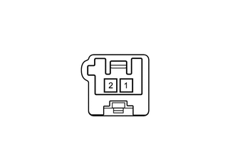
Disconnect the H9 front No. 1 speaker assembly RH connector.
Measure the resistance according to the value(s) in the table below.
Standard Resistance
Tester Connection
Condition
Specified Condition
1 - 2
Always
4.0 Ω
Result
Result
OK
NG
-
CHECK HARNESS AND CONNECTOR (FRONT NO. 3 SPEAKER RH - FRONT NO. 1 SPEAKER RH)
Disconnect the H20 front No. 3 speaker assembly RH connector.
Disconnect the H9 front No. 1 speaker assembly RH connector.
Measure the resistance according to the value(s) in the table below.
Standard Resistance
Tester Connection
Condition
Specified Condition
H20-3 (+) - H9-2
Always
Below 1 Ω
H20-4 (-) - H9-1
Always
Below 1 Ω
H20-3 (+) - Body ground
Always
10 kΩ or higher
H20-4 (-) - Body ground
Always
10 kΩ or higher
Result
Result
OK
NG
NG REPAIR OR REPLACE HARNESS OR CONNECTOR
REPLACE FRONT NO. 3 SPEAKER ASSEMBLY RH
Temporarily replace the front No. 3 speaker assembly RH with a new or normally functioning one.
OK
Malfunction disappears.
Result
Result
OK
NG
OK END (FRONT NO. 3 SPEAKER ASSEMBLY RH IS DEFECTIVE)
INSPECT FRONT NO. 3 SPEAKER ASSEMBLY LH
-
Disconnect the H21 front No. 3 speaker assembly LH connector.
Measure the resistance according to the value(s) in the table below.
Standard Resistance
Tester Connection
Condition
Specified Condition
1 (TWL+) - 3 (+)
Always
Below 1 Ω
2 (TWL-) - 4 (-)
Always
Below 1 Ω
Result
Result
OK
NG
-
INSPECT FRONT NO. 1 SPEAKER ASSEMBLY LH
-
Disconnect the H12 front No. 1 speaker assembly LH connector.
Measure the resistance according to the value(s) in the table below.
Standard Resistance
Tester Connection
Condition
Specified Condition
1 - 2
Always
4.0 Ω
Result
Result
OK
NG
-
CHECK HARNESS AND CONNECTOR (FRONT NO. 3 SPEAKER LH - FRONT NO. 1 SPEAKER LH)
Disconnect the H21 front No. 3 speaker assembly LH connector.
Disconnect the H12 front No. 1 speaker assembly LH connector
Measure the resistance according to the value(s) in the table below.
Standard Resistance
Tester Connection
Condition
Specified Condition
H21-3 (+) - H12-2
Always
Below 1 Ω
H21-4 (-) - H12-1
Always
Below 1 Ω
H21-3 (+) - Body ground
Always
10 kΩ or higher
H21-4 (-) - Body ground
Always
10 kΩ or higher
Result
Result
OK
NG
NG REPAIR OR REPLACE HARNESS OR CONNECTOR
REPLACE FRONT NO. 3 SPEAKER ASSEMBLY LH
Temporarily replace the front No. 3 speaker assembly LH with a new or normally functioning one.
OK
Malfunction disappears.
Result
Result
OK
NG
OK END (FRONT NO. 3 SPEAKER ASSEMBLY LH IS DEFECTIVE)
INSPECT FRONT NO. 4 SPEAKER ASSEMBLY
-
Disconnect the H13 front No. 4 speaker assembly connector.
Measure the resistance according to the value(s) in the table below.
Standard Resistance
Tester Connection
Condition
Specified Condition
1 - 2
Always
6.0 Ω
Result
Result
OK
NG
-
CHECK HARNESS AND CONNECTOR (STEREO COMPONENT AMPLIFIER - SPEAKER)
*1: for RH
*2: for LH
Disconnect the H11 stereo component amplifier assembly connector.
Disconnect the J3*1 and/or K2*2 front No. 2 speaker assembly connector.
Disconnect the L1*1 and/or M1*2 rear No. 1 speaker assembly connector.
Measure the resistance according to the value(s) in the table below.
Standard Resistance
Tester Connection
Condition
Specified Condition
H11-3 (WFL+) - K2-1
Always
Below 1 Ω
H11-4 (RL+) - M1-1
Always
Below 1 Ω
H11-5 (RR+) - L1-1
Always
Below 1 Ω
H11-8 (WFL-) - K2-2
Always
Below 1 Ω
H11-9 (WFR-) - J3-2
Always
Below 1 Ω
H11-10 (WFR+) - J3-1
Always
Below 1 Ω
H11-11 (RL-) - M1-2
Always
Below 1 Ω
H11-12 (RR-) - L1-2
Always
Below 1 Ω
H11-3 (WFL+) - Body ground
Always
10 kΩ or higher
H11-4 (RL+) - Body ground
Always
10 kΩ or higher
H11-5 (RR+) - Body ground
Always
10 kΩ or higher
H11-8 (WFL-) - Body ground
Always
10 kΩ or higher
H11-9 (WFR-) - Body ground
Always
10 kΩ or higher
H11-10 (WFR+) - Body ground
Always
10 kΩ or higher
H11-11 (RL-) - Body ground
Always
10 kΩ or higher
H11-12 (RR-) - Body ground
Always
10 kΩ or higher
Result
Result
OK
NG
NG REPAIR OR REPLACE HARNESS OR CONNECTOR
INSPECT FRONT NO. 2 SPEAKER ASSEMBLY RH
-
Disconnect the J3 front No. 2 speaker assembly RH connector.
Measure the resistance according to the value(s) in the table below.
Standard Resistance
Tester Connection
Condition
Specified Condition
1 - 2
Always
4.0 Ω
Result
Result
OK
NG
-
INSPECT FRONT NO. 2 SPEAKER ASSEMBLY LH
-
Disconnect the K2 front No. 2 speaker assembly LH connector.
Measure the resistance according to the value(s) in the table below.
Standard Resistance
Tester Connection
Condition
Specified Condition
1 - 2
Always
4.0 Ω
Result
Result
OK
NG
-
INSPECT REAR NO. 1 SPEAKER ASSEMBLY RH
-
Disconnect the L1 rear No. 1 speaker assembly RH connector.
Measure the resistance according to the value(s) in the table below.
Standard Resistance
Tester Connection
Condition
Specified Condition
1 - 2
Always
4.0 Ω
Result
Result
OK
NG
-
INSPECT REAR NO. 1 SPEAKER ASSEMBLY LH
-
Disconnect the M1 rear No. 1 speaker assembly LH connector.
Measure the resistance according to the value(s) in the table below.
Standard Resistance
Tester Connection
Condition
Specified Condition
1 - 2
Always
4.0 Ω
Result
Result
OK
NG
-