VEHICLE STABILITY CONTROL SYSTEM VSC OFF Switch Circuit
| DTC Code | DTC Name |
|---|---|
| VSC OFF Switch Circuit |
DESCRIPTION
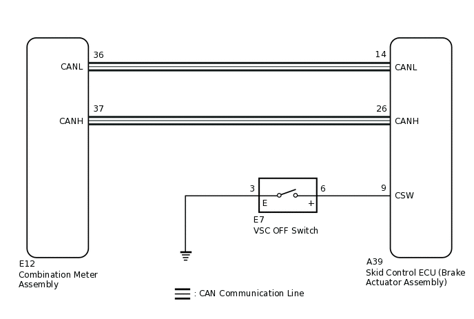
The skid control ECU (brake actuator assembly) is connected to the combination meter assembly via CAN communication.
Pressing the VSC OFF switch turns off TRC operation, and pressing and holding this switch turns off TRC and VSC operation. If TRC and VSC operations are turned off, the TRC OFF indicator light and the VSC OFF indicator light will come on.
WIRING DIAGRAM
CAUTION / NOTICE / HINT
When replacing the skid control ECU (brake actuator assembly), perform system variant learning and acceleration sensor zero point calibration.
PROCEDURE
CHECK CAN COMMUNICATION SYSTEM
Check if CAN communication system DTCs are output.
Result
Result
Proceed to
DTCs are not output.
A
DTCs are output.
B
CHECK IF BRAKE ACTUATOR ASSEMBLY CONNECTOR IS SECURELY CONNECTED
Check if the skid control ECU (brake actuator assembly) connector is securely connected.
OK
The connector is securely connected.
Result
Proceed to
OK
NG
NG CONNECT CONNECTOR TO BRAKE ACTUATOR ASSEMBLY CORRECTLY
READ VALUE USING GTS (TRC/VSC OFF MODE)
Connect the GTS to the DLC3.
Turn the ignition switch to ON.
Select the Data List using the GTS.
Click hereClick hereClick here
Chassis > ABS/VSC/TRC > Data List
Tester Display
Measurement Item
Range
Normal Condition
Diagnostic Note
TRC/VSC Off Mode
TRC/VSC off mode
Normal, TRC OFF, Unknown or VSC OFF
Normal: Normal mode
TRC OFF: TRC off mode
Unknown: Unspecified
VSC OFF: VSC off mode
-
Chassis > ABS/VSC/TRC > Data List
Tester Display
TRC/VSC Off Mode
Check the indicator light and mode condition on the GTS changes according to VSC OFF switch operation.
Standard
Switch Operation
Mode Condition Display
TRC OFF Indicator Light
VSC OFF Indicator Light
Not pressed
Normal
Does not come on
Does not come on
Pressing the VSC OFF switch
TRC OFF
Comes on
Does not come on
Pressing and holding the VSC OFF switch
VSC OFF
Comes on
Comes on
Result
Result
Proceed to
Indicator light and mode condition display do not change.
A
Mode condition display is normal, but indicator light does not change.
B
Indicator light and mode condition display is normal.
C
PERFORM ACTIVE TEST USING GTS (TRC OFF INDICATOR LIGHT AND VSC OFF INDICATOR LIGHT)
Select the Active Test on the GTS.
Click hereClick hereClick here
Chassis > ABS/VSC/TRC > Active Test
Tester Display
Measurement Item
Control Range
Diagnostic Note
TRC(TRAC) OFF Indicator Light
TRC OFF indicator light
Indicator light ON/OFF
Observe combination meter assembly
VSC OFF Indicator Light
VSC OFF indicator light
Indicator light ON/OFF
Observe combination meter assembly
Chassis > ABS/VSC/TRC > Active Test
Tester Display
TRC(TRAC) OFF Indicator Light
Chassis > ABS/VSC/TRC > Active Test
Tester Display
VSC OFF Indicator Light
Check the TRC OFF indicator light and VSC OFF indicator light in the combination meter assembly turn on or off in accordance with GTS operation.
OK
The TRC OFF indicator light and VSC OFF indicator light turn on or off in accordance with GTS operation.
Result
Proceed to
OK
NG
NG INSPECT COMBINATION METER ASSEMBLYClick here
INSPECT VSC OFF SWITCH
-
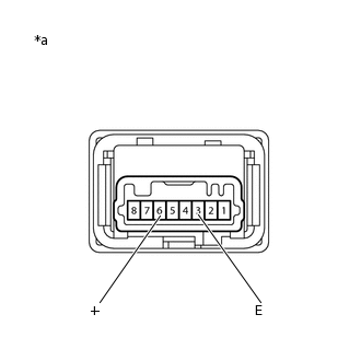
*a
Component without harness connected
(VSC OFF Switch)
Turn the ignition switch off.
Disconnect the E7 VSC OFF switch connector.
Measure the resistance according to the value(s) in the table below.
Standard Resistance
Tester Connection
Condition
Specified Condition
6 (+) - 3 (E)
Switch pushed
Below 1 Ω
6 (+) - 3 (E)
Switch not pushed
10 kΩ or higher
Result
Proceed to
OK
NG
-
CHECK HARNESS AND CONNECTOR (BRAKE ACTUATOR ASSEMBLY - VSC OFF SWITCH)
Disconnect the A39 skid control ECU (brake actuator assembly) connector.
Measure the resistance according to the value(s) in the table below.
Standard Resistance
Tester Connection
Condition
Specified Condition
A39-9 (CSW) - E7-6 (+)
Always
Below 1 Ω
A39-9 (CSW) or E7-6 (+) - Body ground
Always
10 kΩ or higher
E7-3 (E) - Body ground
Always
Below 1 Ω
Tip:If troubleshooting has been carried out according to Problem Symptoms Table, refer back to the table and proceed to the next step before replacing parts.
Result
Proceed to
OK
NG
NG REPAIR OR REPLACE HARNESS OR CONNECTOR
INSPECT COMBINATION METER ASSEMBLY
Turn the ignition switch off.
Perform an Active Test of the combination meter assembly using the GTS.
Click hereClick hereClick here
Body Electrical > Combination Meter > Active Test
Tester Display
VSC TRC Indicator
Body Electrical > Combination Meter > Active Test
Tester Display
Indicat. VSC OFF
Check the combination meter assembly.
OK
The TRC OFF indicator light and VSC OFF indicator light turn on or off in accordance with GTS operation.
Tip:If troubleshooting has been carried out according to Problem Symptoms Table, refer back to the table and proceed to the next step before replacing parts.
Result
Proceed to
OK
NG