STARTER (for 1.0 kW Type) INSPECTION
-
INSPECT STARTER
Note
These tests must be performed within 3 to 5 seconds to prevent the coil from burning out.
-
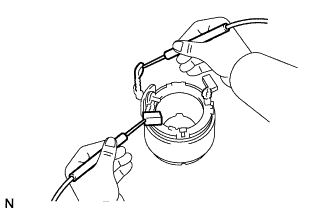
Perform pull-in/holding test.
-
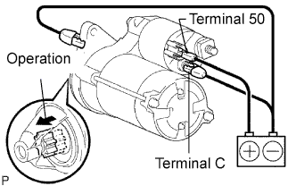
Disconnect the lead wire from terminal C.
-
Connect the battery to the starter assembly as shown in the illustration. Then check that the clutch pinion gear moves outward.
If the clutch pinion gear does not move, replace the magnet starter switch assembly.
-
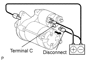
With the battery connected as above with the clutch pinion gear out, disconnect the negative (-) lead from terminal C. Check that the pinion gear remains out.
If the clutch pinion gear moves inward, replace the magnet starter switch assembly.
-

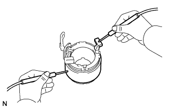
Disconnect the negative (-) lead from the starter body. Check that the clutch pinion gear returns inward.
If the clutch pinion gear does not return inward, replace the magnet starter switch.
-
-

Perform operation test without load.
-
Connect the lead wire to terminal C.
- Torque:
- 9.8 N*m { 100 kgf*cm, 87 in.*lbf }
-
Mount the starter in a vise between aluminum plates.
-
Connect the battery and an ammeter to the starter as shown in the illustration.
-
Check that the starter rotates smoothly and steadily while the pinion gear is moving out. Then measure the current.
Standard current 90 A or less at 11.5 V If the result is not as specified, replace the starter assembly.
-
-
-
INSPECT STARTER ARMATURE ASSEMBLY
-

Check the commutator for an open circuit.
-
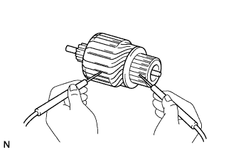
Measure the resistance between any 2 segments of the commutator.
Standard resistance Below 1 Ω If the result is not as specified, replace the armature assembly.
-
-
Check the commutator for short circuit.
-
Measure the resistance between each segment of the commutator and the armature coil core.
Standard resistance 10 kΩ or higher If the result is not as specified, replace the armature assembly.
-
-
Check the commutator for dirt and/or burns on the surface.
If the surface is dirty or burnt, correct with sandpaper (No. 400) or a lathe.
-

Check the commutator circle runout.
-
Place the commutator on V-blocks.
-
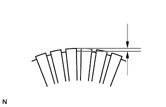
Using a dial gauge, measure the circle runout.
Maximum circle runout 0.05 mm (0.0020 in.) If the circle runout is greater than the maximum, correct it on a lathe.
-
-

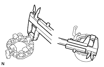
Using a vernier caliper, measure the commutator diameter.
Standard diameter 28 mm (1.10 in.) Minimum diameter 27 mm (1.06 in.) If the diameter is less than the minimum, replace the armature assembly.
-
Using a vernier caliper, measure the undercut depth of the commutator.
Standard depth 0.6 mm (0.024 in.) Minimum depth 0.2 mm (0.008 in.) If the undercut depth is less than the minimum, correct it with a hacksaw blade.
-
-
INSPECT STARTER YOKE ASSEMBLY
-
Inspect for an open circuit.
-
Measure the resistance between the lead wire and field coil brush lead.
Standard resistance Below 1 Ω If the result is not as specified, replace the starter yoke assembly.
-
-
Inspect for a short circuit.
-
Measure the resistance between the field coil brush lead and starter yoke body.
Standard resistance 10 kΩ or higher If the result is not as specified, repair or replace the starter yoke assembly.
-
-
-
INSPECT BRUSH LENGTH
-
Using a vernier caliper, measure the brush length.
Standard brush length 14.0 mm (0.551 in.) Minimum brush length 9.0 mm (0.354 in.) If the length is less than the minimum, replace the brush holder assembly and starter yoke assembly.
-
-
INSPECT STARTER BRUSH HOLDER ASSEMBLY
-
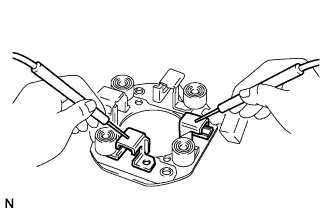
Inspect the brush insulation.
-
Measure the resistance between the positive (+) and negative (-) brush holders.
Standard resistance 10 kΩ or higher If the result is not as specified, replace the brush holder assembly.
-
-

Take a pull scale reading the instant the brush spring separates from the brush.
Standard spring load 13.7 to 17.6 N (1.4 to 1.8 kgf, 3.1 to 4.0 lbf) Minimum spring load 8.8 N (0.9 kgf, 2.0 lbf) If the spring load is less than the minimum, replace the brush holder assembly.
-
-
INSPECT GEAR TEETH
-
Check the gear teeth on the planetary gears, internal gear and starter clutch pinion gear for wear or damage.
If a planetary gear or the internal gear is damaged, replace it.
If the starter clutch pinion gear teeth are damaged, replace the starter clutch and also inspect the flywheel ring gear for wear or damage.
-
-
INSPECT STARTER CLUTCH SUB-ASSEMBLY
-
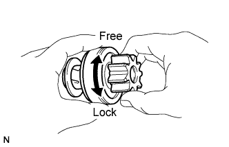
Rotate the clutch pinion gear clockwise and check that it turns freely. Try to rotate the clutch pinion gear counterclockwise and check that it locks.
If necessary, replace the starter clutch sub-assembly.
-
-
INSPECT PLUNGER
-

Push in the plunger and check that it returns quickly to its original position.
If necessary, replace the magnetic starter switch assembly.
-
-
INSPECT MAGNET STARTER SWITCH ASSEMBLY
-
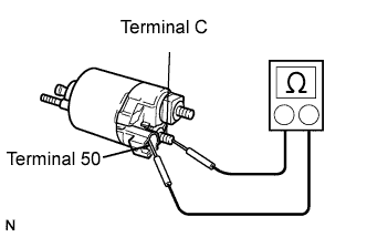
Inspect the pull-in coil.
-
Measure the resistance between terminal 50 and terminal C.
Standard resistance Below 1 Ω If the result is not as specified, replace the magnet starter switch assembly.
-
-
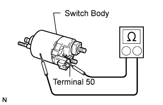
Inspect the holding coil.
-
Measure the resistance between terminal 50 and switch body.
Standard resistance Below 2 Ω If the result is not as specified, replace the magnet starter switch assembly.
-
-