FRONT SUSPENSION CROSSMEMBER TWO-DIMENSIONAL DISTANCE
Tip:
Length measurements are indicated at the points where the arrows extending from the zero point intersect the lines that extend towards the outside of the illustration from each point.
In cases in which only one dimension is given, left and right are symmetrical.
For symbols, capital letters indicate right side of vehicle, small letters indicate left side of vehicle (seen from rear).
Symbol |
Name |
Hole Diameter mm (in.) |
|---|---|---|
A, a |
Front Suspension Lower Arm Installation Hole |
φ13.5 (0.53) |
B, b |
Front Suspension Crossmember Installation Hole |
φ19 (0.75) |
C, c |
Steering Gear Box Installation Hole |
φ14.5 (0.57) |
D, d |
Front Suspension Crossmember Installation Hole |
φ16 (0.63) |
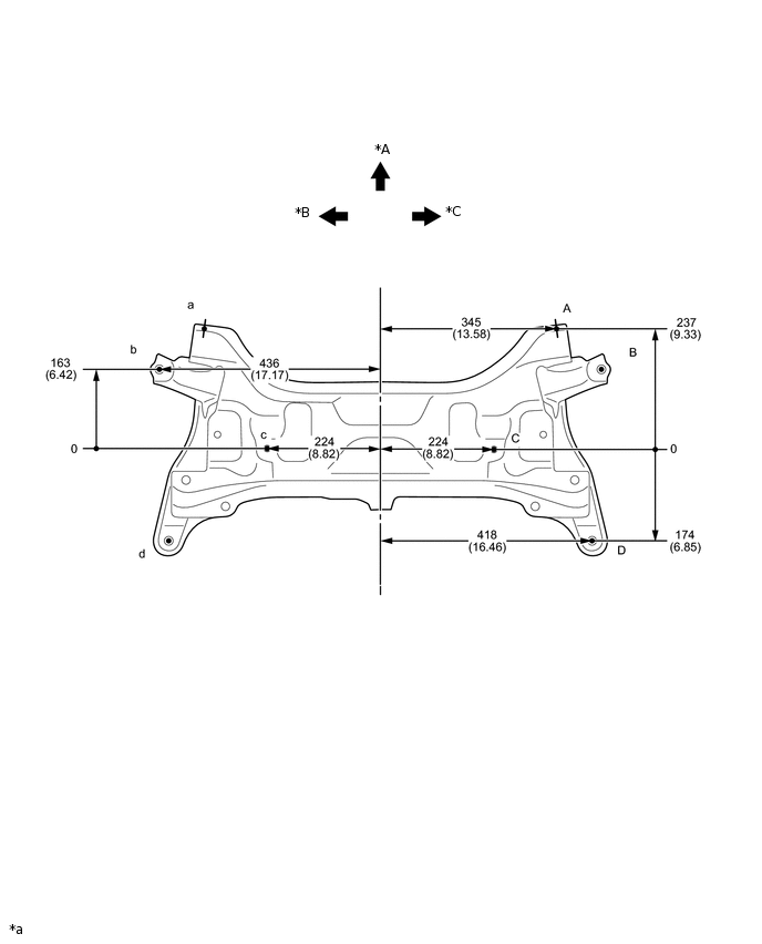
*A |
FRONT |
*B |
LH |
*C |
RH |
- |
- |
*a |
mm (in.) |
- |
- |
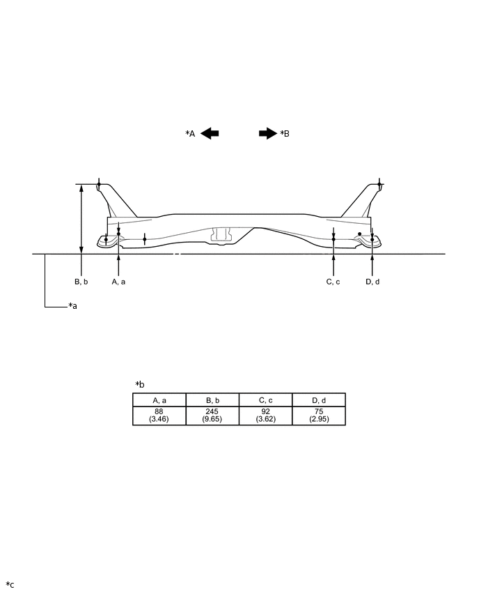
*A |
LH |
*B |
RH |
*a |
Imaginary Datum Line |
*b |
Height from Imaginary Datum Line |
*c |
mm (in.) |
- |
- |