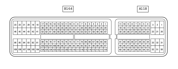
ECD SYSTEM TERMINALS OF ECM
CHECK ECM
Measure the voltage, resistance or waveform of the ECM connector.
Tip:The standard voltage, resistance and waveform of each ECM terminal is shown in the table below.
In the table, first follow the information in "Condition". Look at "Terminal No. (Symbol)" for the terminals to be inspected. The standard voltage, resistance and waveform between the terminals is shown in "Specified Condition".
Use the illustration above as a reference for the ECM terminals.
Terminal No. (Symbol)
Wiring Color
Terminal Description
Condition
Specified Condition
A118-1 (+B) - B164-109 (E1)
B - BR
Power source of ECM
Ignition switch ON
11 to 14 V
A118-2 (BATT) - B164-109 (E1)
W - BR
Battery (for measuring the battery voltage and for the ECM memory)
Always
11 to 14 V
A118-4 (CANN) - B164-109 (E1)
SB - BR
CAN communication line
Ignition switch ON
Pulse generation
(See waveform 1)
A118-5 (CANP) - B164-109 (E1)
B - BR
CAN communication line
Ignition switch ON
Pulse generation
(See waveform 2)
A118-6 (CANL) - B164-109 (E1)
W - BR
CAN communication line
Ignition switch ON
Pulse generation
(See waveform 1)
A118-7 (CANH) - B164-109 (E1)
B - BR
CAN communication line
Ignition switch ON
Pulse generation
(See waveform 2)
A118-12 (W) - B164-109 (E1)
LG - BR
MIL
MIL illuminated
Below 3 V
MIL not illuminated
11 to 14 V
A118-13 (TACH) - B164-109 (E1)
GR - BR
Engine speed
Idling
Pulse generation
(See waveform 3)
A118-14 (SPD) - B164-109 (E1)
V - BR
Speed signal from combination meter
Ignition switch ON, drive wheels rotating slowly
Pulse generation
(See waveform 4)
A118-20 (+B2) - B164-109 (E1)
B - BR
Power source of ECM
Ignition switch ON
11 to 14 V
A118-21 (FANH) - B164-109 (E1)
W - BR
FAN NO. 1, 2 relay
Idling with high engine coolant temperature
Below 1.5 V
A118-22 (FANL) - B164-109 (E1)
R - BR
FAN NO. 3 relay
Ignition switch ON
11 to 14 V
Idling with A/C on
or high engine coolant temperature
Below 1.5 V
A118-25 (IGSW) - B164-109 (E1)
B - BR
Ignition switch
Ignition switch ON
11 to 14 V
A118-26 (TC) - B164-109 (E1)
P - BR
Terminal TC of DLC3
Ignition switch ON
11 to 14 V
A118-34 (ST1-) - B164-109 (E1)
R - BR
Stop light switch assembly
Ignition switch ON, brake pedal depressed
Below 1.5 V
Ignition switch ON, brake pedal released
7.5 to 14 V
A118-35 (STP) - B164-109 (E1)
L - BR
Stop light switch assembly
Ignition switch ON, brake pedal depressed
7.5 to 14 V
Ignition switch ON, brake pedal released
Below 1.5 V
A118-43 (STA) - B164-109 (E1)
LG - BR
Starter signal
Cranking
5.5 V or higher
A118-44 (IREL) - B164-109 (E1)
G - BR
EDU relay
Idling
0 to 1.5 V
A118-45 (MREL) - B164-109 (E1)
GR - BR
EFI-MAIN relay
Ignition switch ON
11 to 14 V
2 seconds elapsed since ignition switch off
0 to 1.5 V
A118-53 (VPA) - A118-56 (EPA)
W - Y
Accelerator pedal sensor assembly (for engine control)
Ignition switch ON, accelerator pedal fully released
0.5 to 1.1 V
Ignition switch ON, accelerator pedal fully depressed
2.6 to 4.5 V
A118-54 (VPA2) - A118-58 (EPA2)
R - P
Accelerator pedal sensor assembly (for sensor malfunction detection)
Ignition switch ON, accelerator pedal fully released
1.2 to 2.0 V
Ignition switch ON, accelerator pedal fully depressed
3.4 to 4.75 V
A118-55 (VCPA) - A118-56 (EPA)
B - Y
Power source of accelerator pedal sensor assembly (for VPA1)
Ignition switch ON
4.5 to 5.5 V
A118-57 (VCP2) - A118-58 (EPA2)
L - P
Power source of accelerator pedal sensor assembly (for VPA2)
Ignition switch ON
4.5 to 5.5 V
A118-60 (NEO) - B164-109 (E1)
L - BR
Camshaft position sensor signal
Idling with warm engine
Pulse generation
(See waveform 5)
B164-27 (GLDO) - B164-109 (E1)
R - BR
Glow plug controller
Glow plug on
Pulse generation
B164-41 (PCV+) - B164-81 (PCV-)
R - W
Suction control valve
Idling or cranking with warm engine
Pulse generation
(See waveform 6)
B164-42 (M+) - B164-84 (ME01)
P - W-B
Throttle valve duty signal
Engine warmed up, engine racing
Pulse generation
B164-43 (M-) - B164-84 (ME01)
L - W-B
Throttle valve duty signal
Engine warmed up, engine racing
Pulse generation
B164-44 (E02) - Body ground
W-B - -
Earth (ground) circuit of ECM
Always
Below 1 Ω
B164-45 (E01) - Body ground
W-B - -
Earth (ground) circuit of ECM
Always
Below 1 Ω
B164-46 (E05) - Body ground
W-B - -
Earth (ground) circuit of ECM
Always
Below 1 Ω
B164-47 (#4) - B164-109 (E1)
R - BR
Injector assembly
Idling
Pulse generation
(See waveform 7)
B164-48 (#3) - B164-109 (E1)
B - BR
B164-49 (#2) - B164-109 (E1)
G - BR
B164-50 (#1) - B164-109 (E1)
GR - BR
B164-51 (INJF) - B164-109 (E1)
P - BR
Injector driver (EDU)
Idling
Pulse generation
(See waveform 8)
B164-52 (PRD) - B164-109 (E1)
L - BR
Pressure discharge valve drive signal
Engine warmed up, engine racing
Pulse generation
(See waveform 9)
B164-54 (ALT) - B164-109 (E1)
L - BR
Generator assembly duty ratio
Idling
Pulse generation
(See waveform 10)
B164-56 (GLDI) - B164-109 (E1)
V - BR
Glow plug controller
Glow plug on
Pulse generation
B164-58 (GREL) - B164-109 (E1)
L - BR
Glow plug relay assembly
Ignition switch ON
11 to 14 V
B164-62 (IDLO) - B164-109 (E1)
W - BR
Injector driver (EDU)
Idling
4 to 5.5 V
B164-65 (VG) - B164-64 (EVG)
LG - BR
Mass air flow meter assembly power source
Ignition switch ON
Pulse generation
B164-66 (PCR1) - B164-67 (E2M)
P - V
Fuel pressure sensor (main)
Idling
1.8 to 2.1 V
B164-68 (VCM) - B164-67 (E2M)
W - V
Power source of fuel pressure sensor (for PCR1)
Ignition switch ON
4.5 to 5.5 V
B164-69 (VCS) - B164-91 (E2S)
R - G
Power source of fuel pressure sensor (for PCR2)
Ignition switch ON
4.5 to 5.5 V
B164-75 (VCPM) - B164-72 (EPIM)
R - Y
Power source of manifold absolute pressure sensor
Ignition switch ON
4.5 to 5.5 V
B164-75 (VCPM) - B164-74 (EPEX)
R - G
Power source of differential pressure sensor assembly
Ignition switch ON
4.5 to 5.5 V
B164-76 (THCF) - B164-77 (ETCF)
P - V
Exhaust gas temperature sensor
Engine warmed up, idling
4.6 to 4.9 V
B164-78 (VCG) - B164-109 (E1)
B - BR
Power source of camshaft position sensor
Ignition switch ON
4.5 to 5.5 V
B164-80 (G2+) - B164-79 (G2-)
R - W
Camshaft position sensor
Idling
Pulse generation
(See waveform 11)
B164-82 (GE01) - Body ground
BR - -
Shielded earth (ground) circuit of throttle actuator
Always
Below 1 Ω
B164-83 (EOPV) - B164-109 (E1)
L - BR
Oil pressure switching valve assembly
Idling
Below 1.5 V
B164-85 (EGM-) - B164-84 (ME01)
W - W-B
Electric EGR control valve assembly duty signal
Engine warmed up, idling
Pulse generation
B164-86 (EGM+) - B164-84 (ME01)
B - W-B
Electric EGR control valve assembly duty signal
Engine warmed up, idling
Pulse generation
B164-93 (VPOP) - B164-70 (EPOP)
B - W
Power source of oil pressure sender gauge assembly
Ignition switch ON
4.5 to 5.5 V
B164-94 (VCEG) - B164-95 (EEGL)
G - R
EGR valve position sensor
Ignition switch ON
4.5 to 5.5 V
B164-97 (VCVL) - B164-96 (EVLU)
B - W
Throttle position sensor
Ignition switch ON
4.98 to 5.02 V
B164-98 (PEX) - B164-74 (EPEX)
L - G
Differential pressure sensor assembly
Ignition switch ON
0.4 to 4.8 V
B164-101 (VNVC) - B164-100 (VNE2)
B - Y
Power source of nozzle vane position sensor
Ignition switch ON
4.5 to 5.5 V
B164-103 (NE+) - B164-102 (NE-)
R - G
Crankshaft position sensor
Idling
Pulse generation
(See waveform 11)
B164-104 (HAF2) - B164-46 (E05)
G - W-B
Air fuel ratio sensor heater
Ignition switch ON
11 to 14 V
B164-105 (FIV) - B164-109 (E1)
B - BR
Exhaust fuel addition injector assembly
Engine warmed up, idling, every 1 to 2 minutes
Pulse generation
B164-106 (ECBV) - B164-109 (E1)
Y - BR
No. 1 vacuum switching valve assembly (for EGR cooler)
No. 1 vacuum switching valve assembly (for EGR cooler) on
Below 1.5 V
No. 1 vacuum switching valve assembly (for EGR cooler) off
11 to 14 V
B164-107 (M-) - B164-109 (E1)
R - BR
DC motor (turbocharger sub-assembly)
Idling with warm engine
Pulse generation
(See waveform 12)
B164-108 (M+) - B164-109 (E1)
W - BR
DC motor (turbocharger sub-assembly)
Idling with warm engine
Pulse generation
(See waveform 12)
B164-109 (E1) - Body ground
BR - -
Earth (ground) circuit of ECM
Always
Below 1 Ω
B164-110 (THA) - B164-87 (ETHA)
L - BR
Intake air temperature sensor
Idling, intake air temperature 0 to 80°C (32 to 176°F)
0.5 to 3.4 V
B164-111 (THW) - B164-88 (ETHW)
B - BR
Engine coolant temperature sensor
Idling, engine coolant temperature 60 to 120°C (140 to 248°F)
0.2 to 1.0 V
B164-112 (THF) - B164-89 (ETHF)
GR - BR
Fuel temperature sensor
Ignition switch ON
0.5 to 3.4 V
B164-113 (THIA) - B164-90 (ETHI)
Y - G
Intake air temperature sensor (turbo)
Idling, intake air temperature at 0 to 80°C (32 to 176°F)
0.5 to 3.4 V
B164-114 (PCR2) - B164-91 (E2S)
GR - G
Fuel pressure sensor (sub)
Idling
1.2 to 1.5 V
B164-116 (POP) - B164-70 (EPOP)
G - W
Oil pressure sender gauge assembly
Idling
0.1 to 0.9 V
B164-117 (PIM) - B164-72 (EPIM)
G - Y
Manifold absolute pressure sensor
Negative pressure of 40 kPa (300 mmHg, 11.8 in.Hg) applied
0.3 to 0.9 V
Atmospheric pressure
0.8 to 1.4 V
Positive pressure of 69 kPa (518 mmHg, 20.3 in.Hg) applied
1.6 to 2.2 V
B164-118 (EGLS) - B164-95 (EEGL)
L - R
EGR valve position sensor
Ignition switch ON
1.03 to 1.37 V
B164-119 (VLU) - B164-96 (EVLU)
LG - W
Throttle position sensor
Ignition switch ON, throttle valve fully opened
3.6 to 4.2 V
B164-121 (THCO) - B164-120 (ETCO)
P - BR
No. 3 Exhaust gas temperature sensor
Engine warmed up, idling
4.6 to 4.9 V
B164-122 (THCI) - B164-99 (ETCI)
L - BR
No. 2 Exhaust gas temperature sensor
Engine warmed up, idling
4.6 to 4.9 V
B164-123 (RLFF) - B164-109 (E1)
V - BR
Pressure discharge valve confirmation signal
Engine warmed up, engine racing
Pulse generation
(See waveform 9)
B164-124 (VNA) - B164-100 (VNE2)
G - Y
Nozzle vane position sensor
Ignition switch ON
2.3 to 2.7 V
B164-125 (AF2+) - B164-46 (E05)
L - W-B
Air fuel ratio sensor
Ignition switch ON
2.0 to 2.5 V
B164-126 (AF2-) - B164-46 (E05)
Y - W-B
Air fuel ratio sensor
Ignition switch ON
2.0 to 2.5 V
-
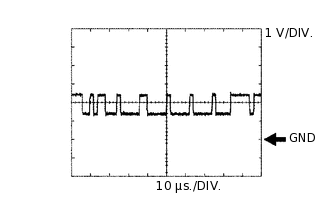
Using an oscilloscope, check waveform 1.
Waveform 1
CAN Communication Signal
ECM Terminal Name
Between CANL and E1
Between CANN and E1
Tester Range
1 V/DIV., 10 μs./DIV.
Condition
Ignition switch ON
Tip:The waveform varies depending on the CAN communication signal.
-
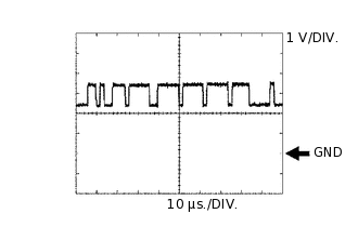
Using an oscilloscope, check waveform 2.
Waveform 2
CAN Communication Signal
ECM Terminal Name
Between CANH and E1
Between CANP and E1
Tester Range
1 V/DIV., 10 μs./DIV.
Condition
Ignition switch ON
Tip:The waveform varies depending on the CAN communication signal.
-
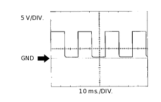
Using an oscilloscope, check waveform 3.
Waveform 3
Engine Speed Signal
ECM Terminal Name
Between TACH and E1
Tester Range
5 V/DIV., 10 ms./DIV.
Condition
Idling
Tip:The wavelength becomes shorter as the engine speed increases.
-
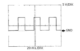
Using an oscilloscope, check waveform 4.
waveform 4
Vehicle Speed Signal
ECM Terminal Name
Between SPD and E1
Tester Range
5 V/DIV., 20 ms./DIV.
Condition
Ignition switch ON, driving wheels rotating slowly
Tip:The wavelength becomes shorter as the vehicle speed increases.
-
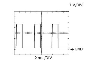
Using an oscilloscope, check waveform 5.
waveform 5
Vehicle Speed Signal
ECM Terminal Name
Between NEO and E1
Tester Range
1 V/DIV., 2 ms./DIV.
Condition
Idling with warm engine
Tip:The wavelength becomes shorter as the vehicle speed increases.
-
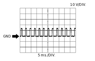
Using an oscilloscope, check waveform 6.
Waveform 6
Suction Control Valve Signal
ECM Terminal Name
Between PCV+ and PCV-
Tester Range
10 V/DIV., 5 ms./DIV.
Condition
Idling or cranking with warm engine
Tip:The waveform varies depending on the suction control valve operation.
-
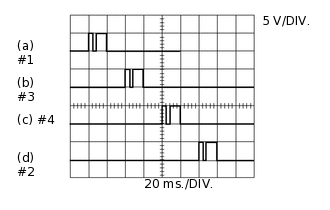
Using an oscilloscope, check waveform 7.
Waveform 7
No. 1 Injector Assembly Injection Signal
No. 2 Injector Assembly Injection Signal
No. 3 Injector Assembly Injection Signal
No. 4 Injector Assembly Injection Signal
ECM Terminal Name
(a) Between #1 and E1
(b) Between #3 and E1
(c) Between #4 and E1
(d) Between #2 and E1
Tester Range
5 V/DIV., 20 ms./DIV.
Condition
Idling
Tip:The waveform varies depending on the injector injection.
-
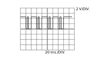
Using an oscilloscope, check waveform 8.
Waveform 8
Injector Injection Confirmation Signal
ECM Terminal Name
Between INJF and E1
Tester Range
2 V/DIV., 20 ms./DIV.
Condition
Idling
Tip:The waveform varies depending on the injector injection.
-
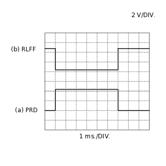
Using an oscilloscope, check waveform 9.
Waveform 9
Pressure Discharge Valve Drive Signal and Pressure Discharge Confirmation Signal
ECM Terminal Name
(a) Between PRD and E1
(b) Between RLFF and E1
Tester Range
2 V/DIV., 1 ms./DIV.
Condition
Engine warmed up, engine racing
Tip:The waveform becomes shorter as the engine speed.
-
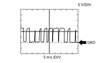
Using an oscilloscope, check waveform 10.
Waveform 10
Generator Assembly Signal
ECM Terminal Name
Between ALT and E1
Tester Range
5 V/DIV., 5 ms./DIV.
Condition
Idling
-
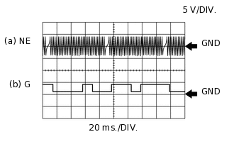
Using an oscilloscope, check waveform 11.
Waveform 11
Crankshaft Position Sensor and Camshaft Position Sensor Signal
ECM Terminal Name
(a) Between NE+ and NE-
(b) Between G2+ and G2-
Tester Range
5 V/DIV., 20 ms./DIV.
Condition
Idling
Tip:The waveform varies depending on the engine speed.
-
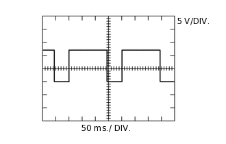
Using an oscilloscope, check waveform 12.
Waveform 12
DC Motor Positive Terminal and DC Motor Negative Terminal
ECM Terminal Name
Between M+ and E1
Between M- and E1
Tester Range
5 V/DIV., 50 ms./DIV.
Condition
Idling with warm engine
Tip:The waveform varies depending on turbocharger sub-assembly operation.