EGR COOLER INSTALLATION
PROCEDURE
INSTALL EGR VALVE ASSEMBLY
INSTALL EGR COOLER ASSEMBLY WITH EGR VALVE ASSEMBLY
Install a new water pipe to the EGR cooler assembly.
Install a new gasket to the No. 2 EGR pipe sub-assembly.
Tip:Make sure that the claw of the gasket faces the No. 2 EGR pipe sub-assembly.
Temporarily install the EGR cooler assembly with EGR valve assembly with the 7 bolts.
-
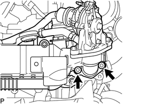
Using a T45 "TORX" socket wrench, tighten the 2 bolts.
5.0 N*m
51 kgf*cm
44 in.*lbf
Loosen the 2 bolts 90°.
-

Tighten the 7 bolts labeled A, B and C, and then 2 nuts in the order shown in the illustration.
for bolt A
13 N*m
133 kgf*cm
10 ft.*lbf
for bolt B
19 N*m
194 kgf*cm
14 ft.*lbf
for bolt C
8.0 N*m
82 kgf*cm
71 in.*lbf
Table 1. Text in Illustration 
Bolt A

Bolt B

Bolt C
Tip:When tightening the bolts labeled A, use a T45 "TORX" socket wrench.
When tightening the bolts labeled B, use a 6 mm hexagon wrench.
Connect the vacuum hoses to the EGR cooler assembly.
Connect the hose clamp to the EGR cooler hose.
Attach the clamp and connect the engine wire to the EGR valve assembly.
Connect the EGR valve assembly connector.
INSTALL NO. 1 EXHAUST MANIFOLD HEAT INSULATOR
Install the No. 1 exhaust manifold heat insulator with the 2 bolts.
8.0 N*m
82 kgf*cm
71 in.*lbf
Attach the 2 clamps and connect the engine wire.
Attach the 2 clamps and connect the air fuel ratio sensor.
-
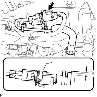
Lower the air fuel ratio sensor connector to the position shown in the illustration and connect the air fuel ratio sensor connector.
Table 2. Text in Illustration *1
Air Fuel Ratio Sensor
*2
Bracket
*a
1.5 mm (0.0591 in.) or less
INSTALL NO. 1 TURBO INSULATOR
CONNECT FUEL FEED PIPE SUB-ASSEMBLY
Connect the fuel feed pipe sub-assembly to the fuel pipe clamp.
Connect the vacuum hose to the No. 2 fuel hose.
Connect the fuel feed pipe sub-assembly with the 2 bolts.
8.0 N*m
82 kgf*cm
71 in.*lbf
Attach the 2 clamps and connect the engine wire.
CONNECT NO. 1 AIR TUBE ASSEMBLY
INSTALL NO. 4 WATER BY-PASS HOSE
CONNECT ENGINE WIRE
CONNECT COMPRESSOR OUTLET ELBOW
INSTALL AIR CLEANER CASE SUB-ASSEMBLY
INSTALL AIR CLEANER FILTER ELEMENT SUB-ASSEMBLY
INSTALL AIR CLEANER CAP SUB-ASSEMBLY WITH AIR CLEANER HOSE ASSEMBLY
INSTALL BATTERY CARRIER
INSTALL BATTERY TRAY
INSTALL BATTERY
INSTALL BATTERY INSULATOR
INSTALL BATTERY CLAMP SUB-ASSEMBLY
INSTALL RADIATOR SUPPORT OPENING COVER
CONNECT CABLE TO POSITIVE BATTERY TERMINAL
CONNECT CABLE TO NEGATIVE BATTERY TERMINAL
Note:When disconnecting the cable, some systems need to be initialized after the cable is reconnected (Click here).
ADD ENGINE COOLANT
INSPECT FOR COOLANT LEAK
INSTALL NO. 1 ENGINE UNDER COVER
PERFORM INITIALIZATION
Perform EGR learning value reset (Click here).