WIPER AND WASHER SYSTEM(w/ Rain Sensor) Rain Sensor Circuit
| DTC Code | DTC Name |
|---|---|
| Rain Sensor Circuit |
DESCRIPTION
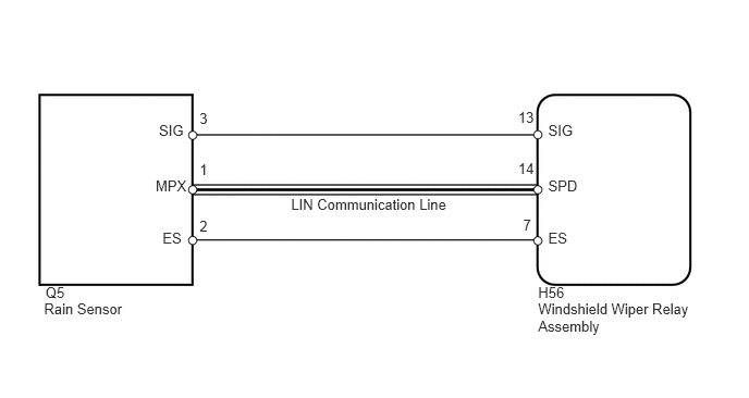
The windshield wiper relay assembly receives a signal from the rain sensor to control the auto wiper system.
WIRING DIAGRAM
PROCEDURE
CHECK COMMUNICATION FUNCTION OF LIN COMMUNICATION SYSTEM
Check that the LIN communication system is normal. (Click here)
OK
LIN communication system is normal.
CHECK HARNESS AND CONNECTOR (WINDSHIELD WIPER RELAY - RAIN SENSOR)
Disconnect the H56 relay connector.
Disconnect the Q5 sensor connector.
Measure the resistance according to the value(s) in the table below.
Standard Resistance
Tester Connection
Condition
Specified Condition
H56-13 (SIG) - Q5-3 (SIG)
Always
Below 1 Ω
Q5-3 (SIG) - Body ground
Always
10 kΩ or higher
H56-7 (ES) - Q5-2 (ES)
Always
Below 1 Ω
Q5-2 (ES) - Body ground
Always
10 kΩ or higher
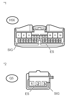
Table 1. Text in Illustration *1
Front view of wire harness connector
(to Windshield Wiper Relay Assembly)
*2
Front view of wire harness connector
(to Rain Sensor)
REPAIR OR REPLACE HARNESS OR CONNECTOR
CHECK WINDSHIELD WIPER RELAY ASSEMBLY
-
Remove the wiper relay with its connector still connected (Click herefor LHD,Click herefor RHD).
Measure the voltage according to the value(s) in the table below.
Standard Voltage
Tester Connection
Switch Condition
Specified Condition
H56-13 (SIG) - H56-7 (ES)
Ignition switch ON
11 to 14 V
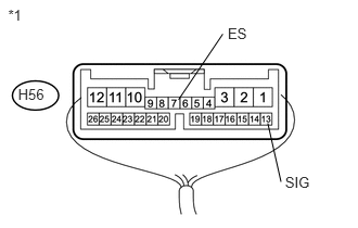
Table 2. Text in Illustration *1
Component with harness connected
(Windshield Wiper Relay Assembly)
Table 3. Result Result
Proceed to
OK
A
NG (for LHD)
B
NG (for RHD)
C
-