VARIABLE GEAR RATIO STEERING SYSTEM, Diagnostic DTC:C1595, C15C4
| DTC Code | DTC Name |
|---|---|
| C1595 | Lost Communication with Steering Angle Sensor Module(SIL) |
| C15C4 | Steering Signal Not Detected |
DESCRIPTION
Signal transmission between the VGRS ECU (front steering control ECU) and steering sensor is performed via serial communication.
If a serial communication error occurs between the VGRS ECU (front steering control ECU) and steering sensor, the ECU stores DTC C1595.
The test mode DTC C15C4 is only stored during test mode.
| DTC No. | Detection Item | DTC Detection Condition | Trouble Area | Warning Indicate | Return-to-normal Condition |
|---|---|---|---|---|---|
| C1595 | Lost Communication with Steering Angle Sensor Module(SIL) | With the engine switch (IG) and a power source voltage of 10 V or higher, serial communication from the steering sensor is interrupted for 3 seconds or more. |
|
Comes on | Engine switch on (IG) again |
| C15C4 | Steering Signal Not Detected | The system enters test mode. |
|
- | - |
WIRING DIAGRAM
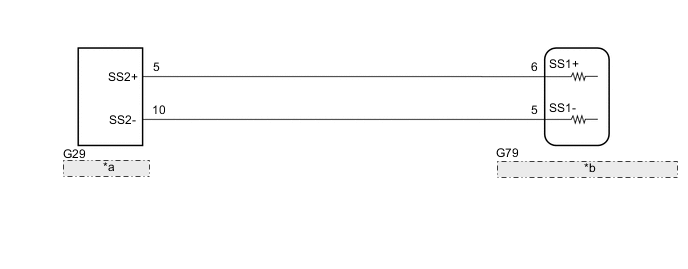
| *a | Steering Sensor |
| *b | VGRS ECU (Front Steering Control ECU) |
CAUTION / NOTICE / HINT
Note
When replacing the VGRS ECU (front steering control ECU), perform actuator angle neutral point calibration and initialization after replacement.
PROCEDURE
-
CHECK DTC
-
Check for DTCs.
Chassis > VGRS > Trouble CodesResult Result Proceed to DTCs C15C1, C15C2 and U0126 are not output A DTCs C15C1, C15C2 and U0126 are output B
B 
REPAIR CIRCUITS INDICATED BY OUTPUT DTCS Click here
A 
-
-
CHECK HARNESS AND CONNECTOR (VGRS ECU (FRONT STEERING CONTROL ECU) - STEERING SENSOR)
-
Turn the engine switch off.
-
Disconnect the G79 VGRS ECU (front steering control ECU) connector.
-
Disconnect the G29 steering sensor connector.
-
Measure the resistance according to the value(s) in the table below.
Standard Resistance Tester Connection Condition Specified Condition G79-5 (SS1-) - G29-10 (SS2-) Always Below 1 Ω G79-6 (SS1+) - G29-5 (SS2+) Always Below 1 Ω G79-5 (SS1-) or G29-10 (SS2-) - Body ground Always 100 kΩ or higher G79-6 (SS1+) or G29-5 (SS2+) - Body ground Always 100 kΩ or higher G79-5 (SS1-) - G79-6 (SS1+) Always 1000 kΩ or higher Result Proceed to OK NG
NG
REPAIR OR REPLACE HARNESS OR CONNECTOR
OK
-
-
CHECK STEERING SENSOR
-
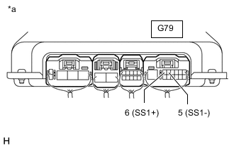
*a Component with harness connected
(VGRS ECU [Front Steering Control ECU])
Reconnect the G79 VGRS ECU (front steering control ECU) connector.
-
Reconnect the G29 steering sensor connector.
-
Start the engine.
-
Measure the voltage according to the value(s) in the table below.
Tech Tips
With the connector connected to the VGRS ECU (front steering control ECU), measure the voltage from the rear of the connector.
Standard Voltage Tester Connection Condition Specified Condition G79-5 (SS1-) - Body ground Steering wheel rotated slowly Pulse waveform that alternates between 0 and 5 V is output G79-6 (SS1+) - Body ground Result Proceed to OK NG
OK
REPLACE VGRS ECU (FRONT STEERING CONTROL ECU) Click here
NG
REPLACE STEERING SENSOR Click here
-