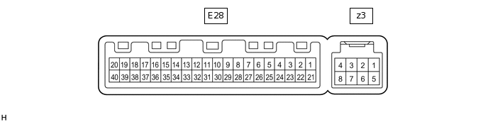
AIR CONDITIONING SYSTEM(for Automatic Air Conditioning System) TERMINALS OF ECU
AIR CONDITIONING AMPLIFIER ASSEMBLY
 Tip:
Tip:Check from the rear of the connector while it is connected to the air conditioning amplifier assembly.
Terminal No.
(Symbol)
Wiring Color
Terminal Description
Condition
Specified Condition
E28-1 (IG+) - E28-14 (GND)
L - BR
Power source (IG)
Ignition switch ON
11 to 14 V
Ignition switch off
Below 1 V
E28-2 (SOL+) - E28-14 (GND)*1
LG - BR
Compressor solenoid operation signal
Engine running
A/C switch: On
Blower switch: LO
Pulse generation
(See waveform 1)
E28-3 (PTC2) - E28-14 (GND)*4
R - BR
Quick heater assembly operation signal
Engine running
Temperature settings: MAX HOT
Ambient temperature: 10 °C or lower
Engine coolant temperature: 65 °C or lower
Light control switch assembly off
Blower switch: On
Below 1 V
Engine running
Temperature settings: MAX HOT
Ambient temperature: 10 °C or lower
Engine coolant temperature: 65 °C or lower
Light control switch assembly on
Blower switch: Off
11 to 14 V
E28-9 (PRE) - E28-13 (SG-2)*1
L - G
Air conditioner pressure sensor signal
Engine running
A/C system operating
Refrigerant pressure: more than 3025 kPa (30.8 kgf/cm2, 439 psi)
4.62 V or higher
Engine running
A/C system operating
Refrigerant pressure: less than 176 kPa (1.8 kgf/cm2, 26 psi)
Below 0.74 V
Engine running
A/C system operating
Refrigerant pressure: less than 3025 kPa (30.8 kgf/cm2, 439 psi) and more than 176 kPa (1.8 kgf/cm2, 26 psi)
0.74 to 4.62 V
E28-10 (S5-3) - E28-13 (SG-2)*1
V - G
Power supply for air conditioner pressure sensor
Ignition switch ON
4.75 to 5.25 V
Ignition switch off
Below 1 V
E28-11 (CANH) - E28-12 (CANL)
Y - W
CAN communication system
CAN communication being performed
Pulse generation
E28-13 (SG-2) - Body ground*1
G - Body ground
Ground for air conditioner pressure sensor
Always
Below 1 V
E28-14 (GND) - Body ground
BR - Body ground
Ground for main power supply
Always
Below 1 V
E28-21 (B) - E28-14 (GND)
W - BR
Power source (Back-up)
Always
11 to 14 V
E28-22 (BLW) - E28-14 (GND)
R - BR
Blower motor speed control signal
Ignition switch ON
Blower switch: LO
Pulse generation
(See waveform 2)
E28-27 (HLS) - E28-14 (GND)*4
V - BR
Light control switch signal
Light control switch: On
11 to 14 V
Light control switch: Off
Below 1 V
E28-29 (TR) - E28-34 (SG-1)*1
GR - V
Cooler (room temp. sensor) thermistor signal
Ignition switch ON
Cabin temperature: 25°C (77°F)
1.8 to 2.2 V
Ignition switch ON
Cabin temperature: 40°C (104°F)
1.2 to 1.6 V
E28-30 (S5-1) - E28-14 (GND)*1
LG - BR
Power supply for cooler (solar sensor) thermistor
Ignition switch ON
4.5 to 5.5 V
Ignition switch off
Below 1 V
E28-32 (TSP) - E28-14 (GND)*1, *2
P - BR
Front passenger side cooler (solar sensor) thermistor signal
Ignition switch ON
Cooler (solar sensor) thermistor subjected to electric light
0.8 to 4.3 V
Ignition switch ON
Cooler (solar sensor) thermistor covered with a cloth
Below 0.8 V
E28-33 (TSD) - E28-14 (GND)*1, *2
L - BR
Driver side cooler (solar sensor) thermistor signal
Ignition switch ON
Cooler (solar sensor) thermistor subjected to electric light
0.8 to 4.3 V
Ignition switch ON
Cooler (solar sensor) thermistor covered with a cloth
Below 0.8 V
E28-33 (TSD) - E28-14 (GND)*1, *3
L - BR
Cooler (solar sensor) thermistor signal
Ignition switch ON
Cooler (solar sensor) thermistor subjected to electric light
0.8 to 4.3 V
Ignition switch ON
Cooler (solar sensor) thermistor covered with a cloth
Below 0.8 V
E28-34 (SG-1) - Body ground*1
V - Body ground
Ground for cooler (room temp. sensor) thermistor
Always
Below 1 V
E28-37 (LIN1) - E28-14 (GND)
SB - BR
LIN communication signal
Ignition switch ON
Pulse generation
E28-39 (PTC3) - E28-14 (GND)*4
P - BR
Quick heater assembly operation signal
Engine running
Temperature settings: MAX HOT
Ambient temperature: 10 °C or lower
Engine coolant temperature: 70 °C or lower
Light control switch assembly off
Blower switch: On
Below 1 V
Engine running
Temperature settings: MAX HOT
Ambient temperature: 10 °C or lower
Engine coolant temperature: 70 °C or lower
Light control switch assembly on
Blower switch: Off
11 to 14 V
E28-40 (PTC1) - E28-14 (GND)*4
W - BR
Quick heater assembly operation signal
Engine running
Temperature settings: MAX HOT
Ambient temperature: 10 °C or lower
Engine coolant temperature: 75 °C or lower
Light control switch assembly off
Blower switch: On
Below 1 V
Engine running
Temperature settings: MAX HOT
Ambient temperature: 10 °C or lower
Engine coolant temperature: 75 °C or lower
Light control switch assembly on
Blower switch: Off
11 to 14 V
z3-2 (BUS G) - Body ground
B - Body ground
Ground for BUS IC
Always
Below 1 V
z3-3 (BUS) - z3-2 (BUS G)
L - B
BUS IC control signal
Ignition switch ON
Pulse generation
z3-4 (B BUS) - z3-2 (BUS G)
R - B
Power supply for BUS IC
Always
11 to 14 V
z3-5 (SGA) - Body ground*1
G - Body ground
Ground for No. 1 cooler thermistor
Always
Below 1 V
z3-6 (TEA) - z3-5 (SGA)*1
G - G
No. 1 cooler thermistor signal
Ignition switch ON
Evaporator temperature: 0°C (32°F)
1.7 to 2.1 V
Ignition switch ON
Evaporator temperature: 15°C (59°F)
0.9 to 1.3 V
*1: w/ Cooler System
*2: for Dual Type
*3: for Single Type
*4: w/ PTC Heater
-
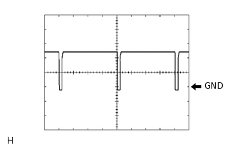
Waveform 1:
Item
Content
Terminal No.
E28-2 (SOL+) - E28-14 (GND)
Tool Setting
5 V/DIV., 500 μs./DIV.
Vehicle Condition
Engine running
A/C switch: On
Blower switch: LO
-
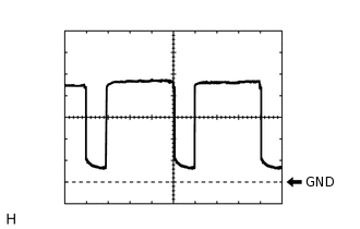
Waveform 2:
Item
Content
Terminal No.
E28-22 (BLW) - E28-14 (GND)
Tool Setting
1 V/DIV., 500 μs./DIV.
Vehicle Condition
Ignition switch ON
Blower switch: LO
AIR CONDITIONING CONTROL ASSEMBLY (for Sedan)
 Tip:
Tip:Check from the rear of the connector while it is connected to the air conditioning control assembly.
Terminal No.
(Symbol)
Wiring Color
Terminal Description
Condition
Specified Condition
E71-1 (ILL-) - Body ground
W-B - Body ground
Illumination signal
Always
Below 1 V
E71-4 (ILL+) - Body ground
LG - Body ground
Illumination signal
Light control switch off
Below 1 V
Light control switch in tail or head position
11 to 14 V
E71-5 (GND) - Body ground
W-B - Body ground
Ground for air conditioning control assembly
Always
Below 1 V
E71-6 (LIN1) - Body ground
SB - Body ground
LIN communication signal
Ignition switch ON
Pulse generation
E71-8 (IG+) - E71-5 (GND)
B - W-B
Power source (IG)
Ignition switch off
Below 1 V
Ignition switch ON
11 to 14 V
AIR CONDITIONING CONTROL ASSEMBLY (for Hatchback, Wagon)
 Tip:
Tip:Check from the rear of the connector while it is connected to the air conditioning control assembly.
Terminal No.
(Symbol)
Wiring Color
Terminal Description
Condition
Specified Condition
E130-1 (GND) - Body ground
W-B - Body ground
Ground for air conditioning control assembly
Always
Below 1 V
E130-4 (ILL+) - Body ground
LG - Body ground
Illumination signal
Light control switch off
Below 1 V
Light control switch in tail or head position
11 to 14 V
E130-5 (ILL-) - Body ground
W-B - Body ground
Illumination signal
Always
Below 1 V
E130-6 (LIN1) - Body ground
SB - Body ground
LIN communication signal
Ignition switch ON
Pulse generation
E130-8 (IG+) - E130-1 (GND)
B - W-B
Power source (IG)
Ignition switch off
Below 1 V
Ignition switch ON
11 to 14 V