SFI SYSTEM, Diagnostic DTC:P0137
| DTC Code | DTC Name |
|---|---|
| P0137 | Oxygen Sensor Circuit Low Voltage (Bank 1 Sensor 2) |
DESCRIPTION
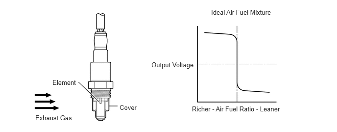
In order to obtain a high purification rate for the carbon monoxide (CO), hydrocarbon (HC) and nitrogen oxide (NOx) components in the exhaust gas, a Three-Way Catalytic Converter (TWC) is used. For the most efficient use of the TWC, the air fuel ratio must be precisely controlled so that it is always close to the stoichiometric air fuel ratio. The heated oxygen sensor (sensor 2) has the characteristic whereby its output voltage changes suddenly in the vicinity of the stoichiometric air fuel ratio. This is used to detect the oxygen concentration in the exhaust gas and provide the ECM with feedback to control the air fuel ratio. When the air fuel ratio becomes lean, the oxygen concentration in the exhaust gas increases. The heated oxygen sensor (sensor 2) informs the ECM of the lean condition (low voltage, i.e. less than 0.45 V). When the air fuel ratio is richer than the stoichiometric air fuel level, the oxygen concentration in the exhaust gas is reduced, and the heated oxygen sensor (sensor 2) informs the ECM of the rich condition (high voltage, i.e. more than 0.45 V). The ECM judges, using the voltage output of the heated oxygen sensor (sensor 2), whether the air fuel ratio is rich or lean and controls the injection time accordingly. If a malfunction of the heated oxygen sensor (sensor 2) causes an output of abnormal voltage, the ECM is unable to perform accurate air fuel ratio control. The heated oxygen sensor (sensor 2) includes a heater which heats the zirconia element. The heater is controlled by the ECM. When the intake air volume is low (the temperature of the exhaust gas is low), a current flows to the heater in order to heat the sensor for accurate oxygen concentration detection.
DTC No. |
Detection Item |
DTC Detection Condition |
Trouble Area |
MIL |
Memory |
|---|---|---|---|---|---|
P0137 |
Oxygen Sensor Circuit Low Voltage (Bank 1 Sensor 2) |
|
|
Comes on |
DTC stored |
*: In order to purge oxygen adsorbed to the TWC, the stoichiometric ratio is controlled to rich side.
WIRING DIAGRAM
Refer to DTC P0130.
CAUTION / NOTICE / HINT
Sensor 1 refers to the sensor closest to the engine assembly.
Sensor 2 refers to the sensor farthest away from the engine assembly.
Read freeze frame data using the GTS. Freeze frame data records the engine condition when malfunctions are detected. When troubleshooting, freeze frame data can help determine if the vehicle was moving or stationary, if the engine was warmed up or not, if the air fuel ratio was lean or rich, and other data from the time the malfunction occurred.
PROCEDURE
CHECK ANY OTHER DTCS OUTPUT (IN ADDITION TO DTC P0137)
Connect the GTS to the DLC3.
Turn the ignition switch to ON.
Turn the GTS on.
Enter the following menus: Powertrain / Engine and ECT / Trouble Codes.
Read the DTCs.
Powertrain > Engine and ECT > Trouble Codes
Result
Result
Proceed to
DTC P0137 is output
A
DTC P0137 and other DTCs are output
B
Tip:If any DTCs other than P0137 are output, troubleshoot those DTCs first.
INSPECT HEATED OXYGEN SENSOR (SENSOR 2)
Inspect the heated oxygen sensor (sensor 2).
Result
Proceed to
OK
NG
CHECK HARNESS AND CONNECTOR (HEATED OXYGEN SENSOR (SENSOR 2) - ECM)
Disconnect the heated oxygen sensor (sensor 2) connector.
Disconnect the ECM connector.
Measure the resistance according to the value(s) in the table below.
Standard Resistance
Tester Connection
Condition
Specified Condition
B18-4 (OX1B) - B31-124 (OX1B)
Always
Below 1 Ω
B18-2 (HT1B) - B31-24 (HT1B)
Always
Below 1 Ω
B18-3 (E1) - B31-123 (E12)
Always
Below 1 Ω
B18-4 (OX1B) or B31-124 (OX1B) - Body ground
Always
10 kΩ or higher
B18-2 (HT1B) or B31-24 (HT1B) - Body ground
Always
10 kΩ or higher
Result
Proceed to
OK
NG
NG REPAIR OR REPLACE HARNESS OR CONNECTOR
REPLACE HEATED OXYGEN SENSOR (SENSOR 2)
Replace the heated oxygen sensor (sensor 2).
Result
Proceed to
NEXT
CHECK WHETHER DTC OUTPUT RECURS (DTC P0137)
Connect the GTS to the DLC3.
Turn the ignition switch to ON.
Turn the GTS on.
Clear the DTCs.
Powertrain > Engine and ECT > Clear DTCs
Turn the ignition switch off and wait for at least 30 seconds.
Start the engine and warm it up.
Turn the GTS on.
Enter the following menus: Powertrain / Engine and ECT / Trouble Codes.
Read the pending DTCs.
Powertrain > Engine and ECT > Trouble Codes
Result
Result
Proceed to
DTC P0137 is output
A
DTCs are not output
B
B END