TOYOTA PARKING ASSIST-SENSOR SYSTEM Clearance Warning ECU Power Source Circuit
| DTC Code | DTC Name |
|---|---|
| Clearance Warning ECU Power Source Circuit |
DESCRIPTION
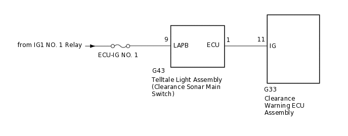
When the telltale light assembly (clearance sonar main switch) is turned on, the on signal is input into the clearance warning ECU assembly.
WIRING DIAGRAM
CAUTION / NOTICE / HINT
Inspect the fuses for circuits related to this system before performing the following inspection procedure.
PROCEDURE
CHECK HARNESS AND CONNECTOR (TELLTALE LIGHT ASSEMBLY - BATTERY)
-
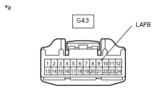
*a
Front view of wire harness connector
(to Telltale Light Assembly)
Disconnect the telltale light assembly connector.
Measure the voltage according to the value(s) in the table below.
Standard Voltage
Tester Connection
Switch Condition
Specified Condition
G43-9 (LAPB) - Body ground
Ignition switch ON
11 to 14 V
G43-9 (LAPB) - Body ground
Ignition switch off
Below 1 V
Result
Proceed to
OK
NG
NG REPAIR OR REPLACE HARNESS OR CONNECTOR
-
CHECK HARNESS AND CONNECTOR (TELLTALE LIGHT ASSEMBLY - CLEARANCE WARNING ECU ASSEMBLY)
Disconnect the G43 telltale light assembly connector.
Disconnect the G33 clearance warning ECU assembly connector.
Measure the resistance according to the value(s) in the table below.
Standard Resistance
Tester Connection
Condition
Specified Condition
G43-1 (ECU) - G33-11 (IG)
Always
Below 1 Ω
G43-1 (ECU) - Body ground
Always
10 kΩ or higher
Result
Proceed to
OK
NG
NG REPAIR OR REPLACE HARNESS OR CONNECTOR
INSPECT TELLTALE LIGHT ASSEMBLY
Remove the telltale light assembly.
Inspect the telltale light assembly.
Result
Proceed to
OK
NG