SPEED LIMITER SYSTEM Speed Limiter System does not Operate
| DTC Code | DTC Name |
|---|---|
| Speed Limiter System does not Operate |
DESCRIPTION
When the speed limiter is turned on using the speed limiter switch, the ECM illuminates the speed limiter indicator and activates the speed limiter system. Each function of the speed limiter system can be activated by operating the cruise control switch. When the cruise control system is operating, the speed limiter system will not operate.
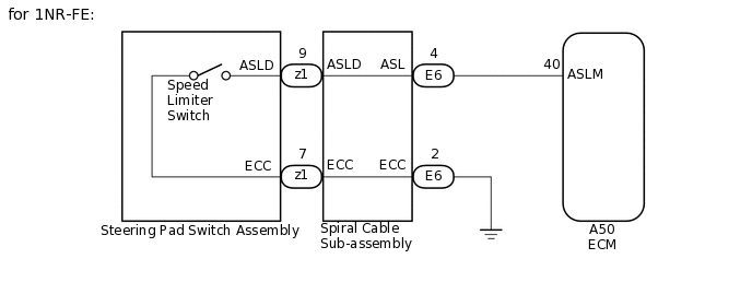
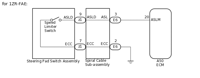
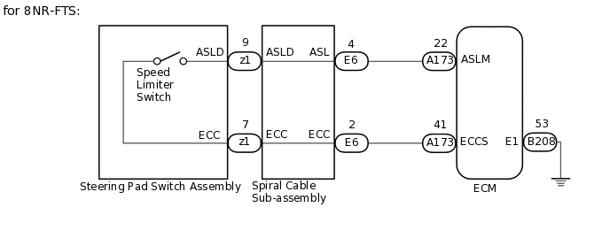
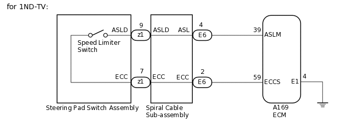
WIRING DIAGRAM

CAUTION / NOTICE / HINT
Before replacing the ECM, refer to Service Bulletin.
PROCEDURE
CHECK CRUISE CONTROL SYSTEM
Turn the ignition switch ON.
Turn the cruise control on using the cruise control switch.
Check the operation of each function by operating the cruise control switch.
except 1ND-TV, 8NR-FTS:Click here
for 1ND-TV:Click here
for 8NR-FTS:Click here
OK
Each function of the cruise control system operates normally.
Result
Proceed to
OK
NG
NG GO TO CRUISE CONTROL SYSTEM
CHECK VEHICLE CONDITION
Choose the model to be inspected.
Result
Result
Proceed to
Other than 8NR-FTS
A
8NR-FTS
B
B READ VALUE USING GTS (ASL SWITCH)Click here
READ VALUE USING GTS (ASL MAIN SWITCH)
Connect the GTS to the DLC3.
Turn the ignition switch to ON.
Turn the GTS on.
Enter the following menus : Powertrain / Cruise Control / Data List / ASL Main Switch.
for 1NR-FE, 1ZR-FAE, 1ND-TV:
According to the display on the GTS, read the Data List.
Powertrain > Cruise Control > Data List
Tester Display
Measurement Item
Range
Normal Condition
Diagnostic Note
ASL Main Switch
Speed limiter switch signal
ON or OFF
ON: Speed limiter switch on
OFF: Speed limiter switch off
-
Powertrain > Cruise Control > Data List
Tester Display
ASL Main Switch
for 1WW:
According to the display on the GTS, read the Data List.
Powertrain > Engine and ECT > Data List
Tester Display
Measurement Item
Range
Normal Condition
Diagnostic Note
ASL Main SW
Speed limiter switch signal
ON or OFF
ON: Speed limiter switch on
OFF: Speed limiter switch off
-
Powertrain > Engine and ECT > Data List
Tester Display
ASL Main SW
OK
The GTS display changes according to switch operation.
Result
Proceed to
OK
NG
OK REPLACE ECM
CHECK HARNESS AND CONNECTOR (SPIRAL CABLE SUB-ASSEMBLY - ECM)
Disconnect the ECM connector.
Disconnect the spiral cable sub-assembly connector.
Measure the resistance according to the value(s) in the table below.
Standard Resistance
Table 1. for 1NR-FE Tester Connection
Condition
Specified Condition
A50-40 (ASLM) - E6-4 (ASL)
Always
Below 1 Ω
A50-40 (ASLM) or E6-4 (ASL) - Body ground
Always
10 kΩ or higher
Table 2. for 1ZR-FAE Tester Connection
Condition
Specified Condition
A50-20 (ASLM) - E6-3 (ASL)
Always
Below 1 Ω
A50-20 (ASLM) or E6-3 (ASL) - Body ground
Always
10 kΩ or higher
Table 3. for 1ND-TV Tester Connection
Condition
Specified Condition
A169-39 (ASLM) - E6-4 (ASL)
Always
Below 1 Ω
A169-59 (ECCS) - E6-2 (ECC)
Always
Below 1 Ω
A169-39 (ASLM) or E6-4 (ASL) - Body ground
Always
10 kΩ or higher
A169-59 (ECCS) or E6-2 (ECC) - Body ground
Always
10 kΩ or higher
Table 4. for 1WW Tester Connection
Condition
Specified Condition
A50-49 (ASLM) - E6-12 (ASL)
Always
Below 1 Ω
A50-42 (ECCS) - E6-2 (ECC)
Always
Below 1 Ω
A50-49 (ASLM) or E6-12 (ASL) - Body ground
Always
10 kΩ or higher
A50-42 (ECCS) or E6-2 (ECC) - Body ground
Always
10 kΩ or higher
Result
Result
Proceed to
OK (except 1ND-TV, 1WW)
A
OK (for 1ND-TV, 1WW)
B
NG
C
B CHECK HARNESS AND CONNECTOR (ECM - BODY GROUND)Click here
C REPAIR OR REPLACE HARNESS OR CONNECTOR
CHECK HARNESS AND CONNECTOR (SPIRAL CABLE SUB-ASSEMBLY - BODY GROUND)
Disconnect the spiral cable sub-assembly connector.
Measure the resistance according to the value(s) in the table below.
Standard Resistance
Tester Connection
Condition
Specified Condition
E6-2 (ECC) - Body ground
Always
Below 1 Ω
Result
Proceed to
OK
NG
NG REPAIR OR REPLACE HARNESS OR CONNECTOR
INSPECT SPIRAL CABLE SUB-ASSEMBLY
Inspect the spiral cable sub-assembly.
w/ VSC:Click here
w/o VSC:Click here
Result
Proceed to
OK
NG
INSPECT STEERING PAD SWITCH ASSEMBLY
Inspect the steering pad switch assembly.
Result
Proceed to
OK
NG
OK REPLACE ECM
for 1NR-FE:Click here
for 1ZR-FAE:Click here
for 1ND-TV:Click here
for 1WW:Click here
for 8NR-FTS:Click here
CHECK HARNESS AND CONNECTOR (ECM - BODY GROUND)
Disconnect the ECM connector.
Measure the resistance according to the value(s) in the table below.
Standard Resistance
Table 5. for 1ND-TV Tester Connection
Condition
Specified Condition
A169-4 (E1) - Body ground
Always
Below 1 Ω
Table 6. for 1WW Tester Connection
Condition
Specified Condition
A50-4 (E1) - Body ground
Always
Below 1 Ω
Result
Proceed to
OK
NG
OK INSPECT SPIRAL CABLE SUB-ASSEMBLYClick here
NG REPAIR OR REPLACE HARNESS OR CONNECTOR
READ VALUE USING GTS (ASL SWITCH)
Connect the GTS to the DLC3.
Turn the ignition switch to ON.
Turn the GTS on.
Enter the following menus : Powertrain / Cruise Control / Data List / ASL SW.
According to the display on the GTS, read the Data List.
Powertrain > Engine > Data List
Tester Display
Measurement Item
Range
Normal Condition
Diagnostic Note
ASL SW
Speed limiter switch signal
ON or OFF
OFF: Speed limiter switch off
ON: Speed limiter switch on
-
Powertrain > Engine > Data List
Tester Display
ASL SW
OK
The GTS display changes according to switch operation.
Result
Proceed to
OK
NG
CHECK HARNESS AND CONNECTOR (SPIRAL CABLE SUB-ASSEMBLY - ECM)
Disconnect the ECM connector.
Disconnect the spiral cable sub-assembly connector.
Measure the resistance according to the value(s) in the table below.
Standard Resistance
Tester Connection
Condition
Specified Condition
A173-22 (ASLM) - E6-4 (ASL)
Always
Below 1 Ω
A173-41 (ECCS) - E6-2 (ECC)
Always
Below 1 Ω
A173-22 (ASLM) or E6-4 (ASL) - Body ground
Always
10 kΩ or higher
A173-41 (ECCS) or E6-2 (ECC) - Body ground
Always
10 kΩ or higher
Result
Proceed to
OK
NG
NG REPAIR OR REPLACE HARNESS OR CONNECTOR
CHECK HARNESS AND CONNECTOR (SPIRAL CABLE SUB-ASSEMBLY - BODY GROUND)
Disconnect the ECM connector.
Measure the resistance according to the value(s) in the table below.
Standard Resistance
Tester Connection
Condition
Specified Condition
B208-53 (E1) - Body ground
Always
Below 1 Ω
Result
Proceed to
OK
NG
OK INSPECT SPIRAL CABLE SUB-ASSEMBLYClick here
NG REPAIR OR REPLACE HARNESS OR CONNECTOR