AIR CONDITIONING SYSTEM(for Manual Air Conditioning System) Blower Motor Circuit
DESCRIPTION
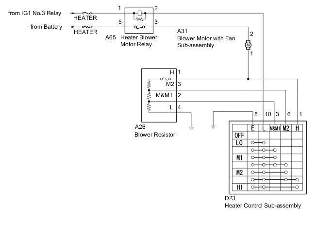
When the heater control sub-assembly is operated, the Heater relay will turn on to allow current to flow to the blower motor and then the motor will start rotating. Operating the heater control sub-assembly switches the current flow between the blower resistor and body ground, thus, shifting the operating speed of the blower motor.
WIRING DIAGRAM
CAUTION / NOTICE / HINT
Note
Inspect the fuses for circuits related to this system before performing the following inspection procedure.
PROCEDURE
-
INSPECT HEATER BLOWER MOTOR RELAY
-
Remove the heater blower motor relay.
-
Inspect the heater blower motor relay Click here.
NG 
REPLACE HEATER BLOWER MOTOR RELAY
OK 
-
-
INSPECT BLOWER MOTOR WITH FAN SUB-ASSEMBLY
-
Disconnect the A31 blower motor with fan sub-assembly connector.
-
Inspect the blower motor with fan sub-assembly Click here.
NG
REPLACE BLOWER MOTOR WITH FAN SUB-ASSEMBLY Click here
OK
-
-
CHECK HARNESS AND CONNECTOR (HEATER BLOWER MOTOR RELAY - BLOWER MOTOR WITH FAN SUB-ASSEMBLY)
-
Measure the resistance according to the value(s) in the table below.
Standard Resistance Tester Connection Condition Specified Condition A65-3 - A31-2 Always Below 1 Ω A65-3 - Body ground Always 10 kΩ or higher
NG
REPAIR OR REPLACE HARNESS OR CONNECTOR
OK
-
-
INSPECT HEATER CONTROL SUB-ASSEMBLY
-
Remove the heater control sub-assembly Click here.
-
Inspect the heater control sub-assembly Click here.
NG
REPLACE HEATER CONTROL SUB-ASSEMBLY Click here
OK
-
-
CHECK HARNESS AND CONNECTOR (HEATER BLOWER MOTOR RELAY - HEATER CONTROL SUB-ASSEMBLY)
-
Disconnect the D23 heater control sub-assembly connector.
-
Measure the resistance according to the value(s) in the table below.
Standard Resistance Tester Connection Condition Specified Condition A65-2 - D23-10 Always Below 1 Ω A65-2 - Body ground Always 10 kΩ or higher
NG
REPAIR OR REPLACE HARNESS OR CONNECTOR
OK
-
-
CHECK HARNESS AND CONNECTOR (BLOWER MOTOR WITH FAN SUB-ASSEMBLY - HEATER CONTROL SUB-ASSEMBLY)
-
Measure the resistance according to the value(s) in the table below.
Standard Resistance Tester Connection Condition Specified Condition A31-1 - D23-1 Always Below 1 Ω A31-1 - Body ground Always 10 kΩ or higher
NG
REPAIR OR REPLACE HARNESS OR CONNECTOR
OK
-
-
CHECK HARNESS AND CONNECTOR (HEATER CONTROL SUB-ASSEMBLY - BODY GROUND)
-
Measure the resistance according to the value(s) in the table below.
Standard Resistance Tester Connection Condition Specified Condition D23-5(E) - Body ground Always Below 1 Ω
NG
REPAIR OR REPLACE HARNESS OR CONNECTOR
OK
-
-
INSPECT BLOWER RESISTOR
-
Remove the blower resister Click here.
-
Inspect the blower resistor Click here.
NG
REPLACE BLOWER RESISTOR Click here
OK
-
-
CHECK HARNESS OR CONNECTOR (HEATER CONTROL SUB-ASSEMBLY - BLOWER RESISTOR)
-
Disconnect the A26 blower resister connector.
-
Measure the resistance according to the value(s) in the table below.
Standard Resistance Tester Connection Condition Specified Condition D23-3(M&M1) - A26-2(M&M1) Always Below 1 Ω D23-6(M2) - A26-3(M2) Always Below 1 Ω D23-3(M&M1) - Body ground Always 10 kΩ or higher D23-6(M2) - Body ground Always 10 kΩ or higher
NG
REPAIR OR REPLACE HARNESS OR CONNECTOR
OK
-
-
CHECK HARNESS OR CONNECTOR (BLOWER MOTOR WITH FAN SUB-ASSEMBLY - BLOWER RESISTOR)
-
Measure the resistance according to the value(s) in the table below.
Standard Resistance Tester Connection Condition Specified Condition A31-1 - A26-1(H) Always Below 1 Ω A31-1 - Body ground Always 10 kΩ or higher
NG
REPAIR OR REPLACE HARNESS OR CONNECTOR
OK
-
-
CHECK HARNESS AND CONNECTOR (BLOWER RESISTOR - BODY GROUND)
-
Measure the resistance according to the value(s) in the table below.
Standard Resistance Tester Connection Condition Specified Condition A26-4(L) - Body ground Always Below 1 Ω
OK
PROCEED TO NEXT SUSPECTED AREA SHOWN IN PROBLEM SYMPTOMS TABLE Click here
NG
REPAIR OR REPLACE HARNESS OR CONNECTOR
-