CAN COMMUNICATION SYSTEM (w/ VSC) Open in One Side of CAN Branch Line
DESCRIPTION
If 2 or more ECUs and/or sensors do not appear on the intelligent tester "Bus Check" screen, one side of the CAN branch wire may be open. (One side of the CANH [branch wire]/CANL [branch wire] of the ECU and/or sensor is open.)
| Symptom | Trouble Area |
|---|---|
| 2 or more ECUs and/or sensors do not appear on intelligent tester "Bus Check" screen. |
|
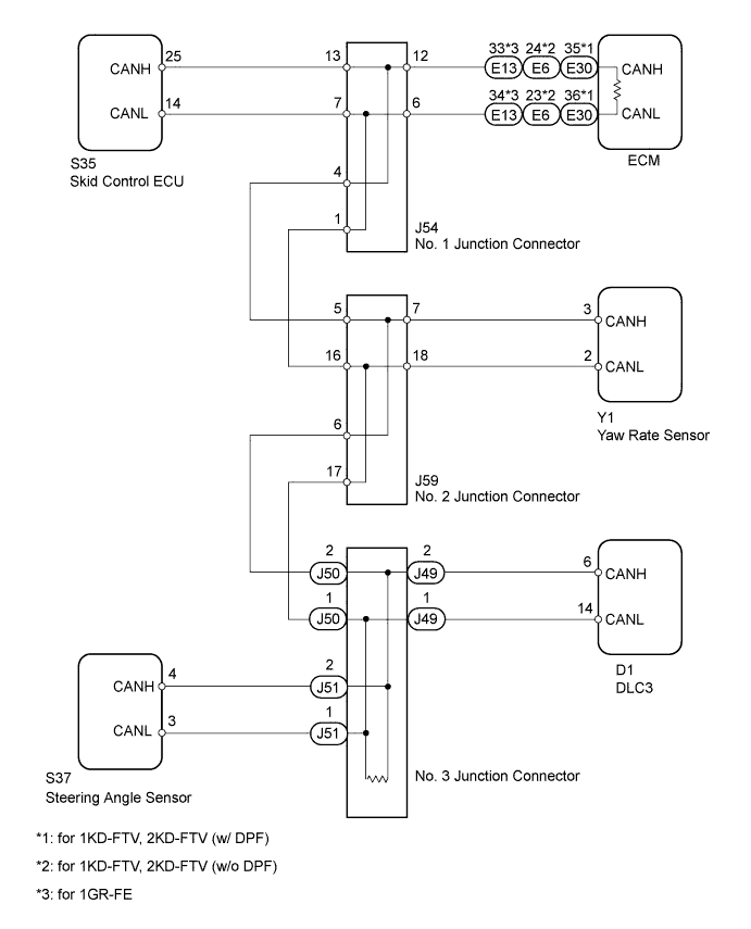
WIRING DIAGRAM
INSPECTION PROCEDURE
Tech Tips
-
Do not remove the ECM and No. 3 junction connector, as they are the end parts of the circuit. If removed, CAN communication will not be possible.
-
The open circuit confirmation of the ECM, No. 3 junction connector and main wire is performed when checking the CAN bus line in "How to Proceed with Troubleshooting". This inspection only has procedures for checking for an open circuit on one side of a CAN branch wire.
PROCEDURE
-
CHECK FOR OPEN IN ONE SIDE OF CAN BRANCH WIRE (SKID CONTROL ECU)
-
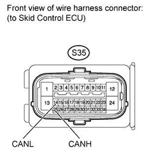
Disconnect the S35 skid control ECU connector.
-
Select "Bus Check" on the intelligent tester.
Result Result Proceed to ABS/VSC/TRC not displayed on intelligent tester. A Several ECUs and sensors other than ABS/VSC/TRC not displayed on intelligent tester. B
B 
CHECK FOR OPEN IN ONE SIDE OF CAN BRANCH WIRE (STEERING ANGLE SENSOR) Click here
A 
-
-
CHECK FOR OPEN IN ONE SIDE OF CAN BRANCH WIRE (SKID CONTROL ECU BRANCH WIRE)
-
Disconnect the cable from the negative (-) battery terminal before measuring the resistances of the main wire and the branch wire.
CAUTION:
Wait at least 90 seconds after disconnecting the cable from the negative (-) battery terminal to disable the SRS system.
Note
When disconnecting the cable from the negative (-) battery terminal, some systems need to be initialized after the cable is reconnected Click here.
-
Measure the resistance according to the value(s) in the table below.
Standard Resistance Tester Connection Switch Condition Specified Condition S35-25 (CANH) - S35-14 (CANL) Ignition switch off 54 to 69 Ω Result Result Proceed to OK (for LHD) A OK (for RHD) B NG C
B 
REPLACE BRAKE ACTUATOR ASSEMBLY (SKID CONTROL ECU) Click here
C
REPAIR OR REPLACE CAN BRANCH WIRE OR CONNECTOR (SKID CONTROL ECU)
A 
REPLACE BRAKE ACTUATOR ASSEMBLY (SKID CONTROL ECU) Click here
-
-
CHECK FOR OPEN IN ONE SIDE OF CAN BRANCH WIRE (STEERING ANGLE SENSOR)
-
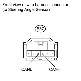
Disconnect the S37 steering angle sensor connector.
-
Select "Bus Check" on the intelligent tester.
Result Result Proceed to Steering Angle Sensor not displayed on intelligent tester. A Several ECUs and sensors other than Steering Angle Sensor not displayed on intelligent tester. B
B
CHECK FOR OPEN IN ONE SIDE OF CAN BRANCH WIRE (YAW RATE SENSOR BRANCH WIRE) Click here
A
-
-
CHECK FOR OPEN IN ONE SIDE OF CAN BRANCH WIRE (STEERING ANGLE SENSOR BRANCH WIRE)
-
Disconnect the cable from the negative (-) battery terminal before measuring the resistances of the main wire and the branch wire.
CAUTION:
Wait at least 90 seconds after disconnecting the cable from the negative (-) battery terminal to disable the SRS system.
Note
When disconnecting the cable from the negative (-) battery terminal, some systems need to be initialized after the cable is reconnected Click here.
-
Measure the resistance according to the value(s) in the table below.
Standard Resistance Tester Connection Switch Condition Specified Condition S37-4 (CANH) - S37-3 (CANL) Ignition switch off 54 to 69 Ω
NG
REPAIR OR REPLACE CAN BRANCH WIRE OR CONNECTOR (STEERING ANGLE SENSOR)
OK
REPLACE SPIRAL CABLE (STEERING ANGLE SENSOR) Click here
-
-
CHECK FOR OPEN IN ONE SIDE OF CAN BRANCH WIRE (YAW RATE SENSOR BRANCH WIRE)
-
Disconnect the cable from the negative (-) battery terminal before measuring the resistances of the main wire and the branch wire.
CAUTION:
Wait at least 90 seconds after disconnecting the cable from the negative (-) battery terminal to disable the SRS system.
Note
When disconnecting the cable from the negative (-) battery terminal, some systems need to be initialized after the cable is reconnected Click here.
-
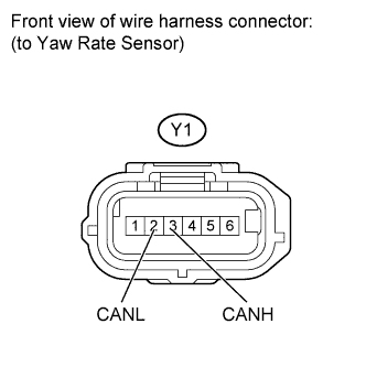
Disconnect the Y1 yaw rate sensor connector.
-
Measure the resistance according to the value(s) in the table below.
Standard Resistance Tester Connection Switch Condition Specified Condition Y1-3 (CANH) - Y1-2 (CANL) Ignition switch off 54 to 69 Ω
NG
REPAIR OR REPLACE CAN BRANCH WIRE OR CONNECTOR (YAW RATE SENSOR)
OK
REPLACE YAW RATE SENSOR Click here
-